IDS-4312(+) Series User Manual
ORing Industrial Networking Corp
23
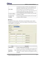
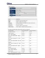
mark bits.
Even
: the number of mark bits in the data is counted, and the
parity bit is asserted or unasserted to obtain an even number
of mark bits.
Mark
: the parity bit is always set to the mark signal condition
(logical 1)
Space
: the last transmitted data bit will always be a logical 0
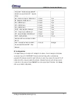
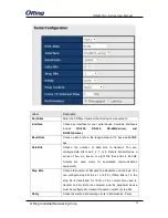
Data Bits
Choose the number of data bits to transmit. You can
configure data bits to be 5, 6, 7, or 8. Data is transmitted as a
series of five, six, seven, or eight bits (five and six bit data
formats are used rarely for specialized communications
equipment).
Stop Bits
Choose the number of bits used to indicate the end of a byte.
You can configure stop bits to be 1 or 2(1.5). If Stop Bits is
1.5, the stop bit is transferred for 150% of the normal time
used to transfer one bit. Both the computer and the peripheral
device must be configured to transmit the same number of
stop bits.
Flow Control
Serial communication consists of hardware flow control and
software flow control, so called as the control is handled by
software or hardware.
XOFF
and
OXN
is software flow control
while
RTS/CTS or DTR/DSR
is hardware flow control.
Choose
XOFF
to tell the computer to stop sending data; then
the receiving side will send an XOFF character over its Tx line
to tell the transmitting side to stop transmitting. Choose
XON
to tell the computer to begin sending data again; then the
receiving side will send an XON character over its Tx line to
tell the transmitting side to resume transmitting. In hardware
flow control mode, when the device is ready to receive data, it
sends a CTS (Clear To Send) signal to the device on the other
end. When a device has something it wants to send, it will
send a RTS (Ready To Send) signal and waits for a CTS
signal to come back its way. These signals are sent apart from
the data itself on separate wires.
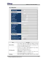
Interface
Choose an interface for your serial device. Available


