Installation
−
11
−
Right angle • hollow shaft type
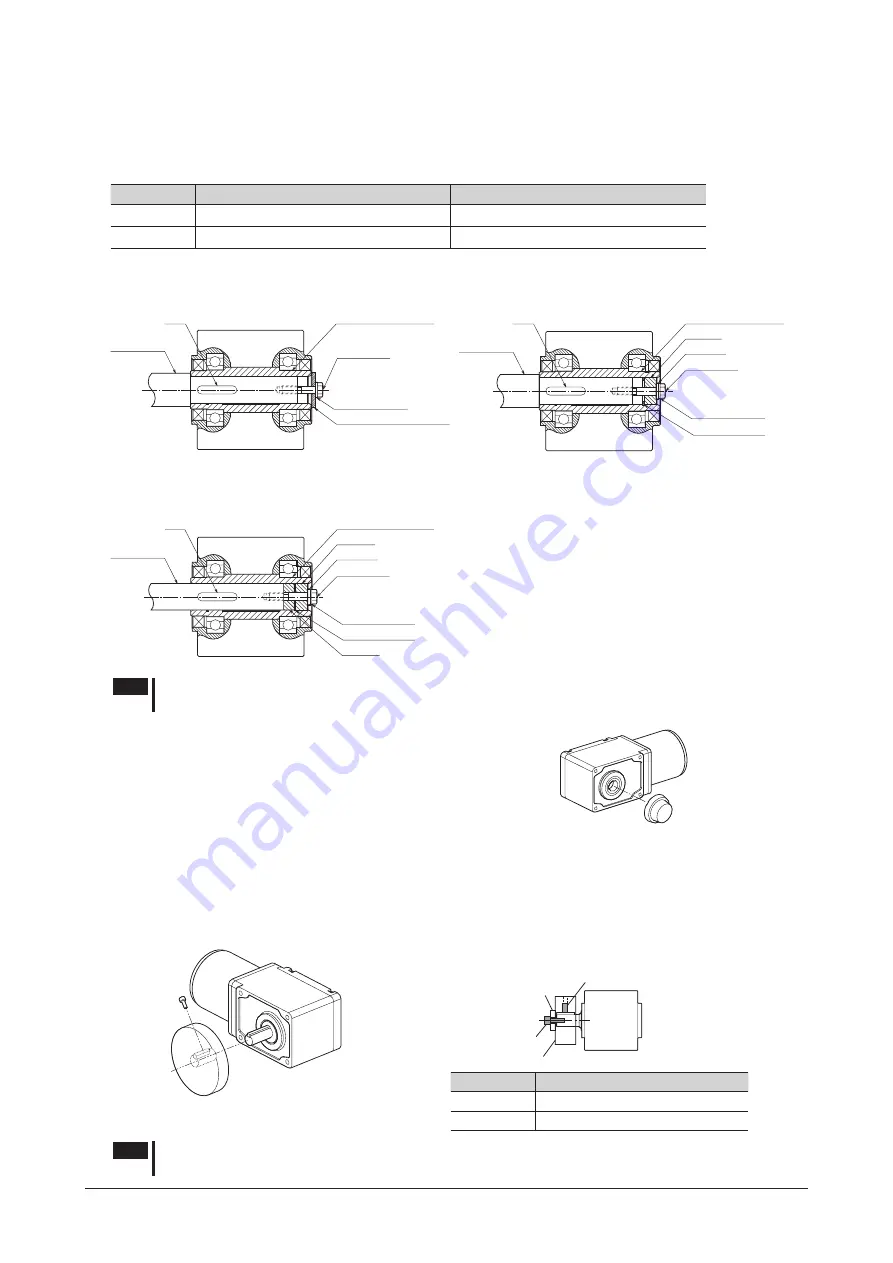
Mounting method of the load varies depending on the load shaft conditions. See the following figures.
The hollow output shaft inside dimension is processed to a tolerance of H8, and incorporates a key slot for load shaft attachment.
A load shaft tolerance of h7 is recommended.
Apply grease on the surface of the load shaft and inner walls of the hollow output shaft to prevent seizure.
Motor model
Hollow shaft inside dimensions (H8)
Recommended load shaft dimensions (h7)
SCM4
Ø18
+0.027
0
mm (Ø0.7087
+0.0011
0
in.)
Ø18
0
-0.018
mm (Ø0.7087
0
-0.0007
in.)
SCM5
Ø25
+0.033
0
mm (Ø0.9843
+0.0013
0
in.)
Ø25
0
-0.021
mm (Ø0.9843
0
-0.0008
in.)
•
Stepped load shaft
Mounting method using end plate
Hollow output shaft
End plate
SCM4
: Plate thickness
3 mm (0.12 in.)
SCM5
: Plate thickness
4 mm (0.16 in.)
Key
Load shaft
Screw
SCM4
: M5
SCM5
: M6
Spring washer
Mounting method using retaining ring
Hollow output shaft
Spacer
Washer
Screw
SCM4
: M5
SCM5
: M6
Spring washer
Retaining ring
Key
Load shaft
•
Non-stepped load shaft
Hollow output shaft
Spacer
Washer
Spring washer
Retaining ring
Spacer
Key
Load shaft
Screw
SCM4
: M5
SCM5
: M6
Note
Do not apply excessive or abrupt force to the hollow output shaft when inserting a load shaft into the
hollow output shaft. Excessive or abrupt force may damage the gearhead internal bearings.
•
Installing the safety cover
After installing the load, attach the safety cover.
When removing the safety cover, insert a plastic stick with a flat tip to the
cutout of the safety cover, and remove.
Safety cover
(Included)
Right angle • solid shaft type
The shaft of the gearhead has been machined to an outer diameter tolerance of h7 and is provided with a key slot for connecting
the transmission parts. When connecting the transmission parts, ensure that the shaft and parts have a clearance fit, and always
fix the parallel key to the output shaft with a screw to prevent the parts from rattling or spinning. With the solid shaft type,
use a tapped hole provided at the end of the output shaft as an auxiliary means for preventing the transfer mechanism from
disengaging.
Fixed screw
Transmission parts
Fixed screw
Screw
Spacer
Transmission parts
•
Example of using the output shaft end tapped hole
Motor model
Output shaft end tapped hole
SCM4
M5 Effective depth 10 mm (0.39 in.)
SCM5
M6 Effective depth 12 mm (0.47 in.)
Note
Do not apply excessive force onto the output shaft of the gearhead using a hammer or other tools. Doing
so may cause damage to the output shaft or bearings.


