Connection
−13−
5.2 Connecting the motor
Connect the motor connector (white) of the motor cable to the CN2, and the sensor connector (black) to the CN3 on
the driver. Check the pin assignment on p.38.
Use a connection cable (supplied or accessory) when extending the wiring distance between the motor and driver.
The connection cable can be connected up to 2 pieces. The wiring distance between the motor and driver can be
extended to a maximum of 10.5 m (34.4 ft.).
Note
Ensure that the connector plugged in securely. Insecure connections may cause malfunction or
damage to the motor or driver.
5.3 Grounding
Be sure to ground the product.
Ground the motor and driver using the Protective Earth Terminal (PE) respectively.
Note
Ground the product securely. Failure to do so may result in electric shock or damage to the
product.
The product will tend to be electrified especially in a dry environment, so it may be damaged by
static electricity.
Motor
Connect the Protective Earth Terminal (PE) on the motor to the ground near the motor.
Minimize the wiring length of the ground cable.
Ground terminal
PE
•
Applicable crimp terminal:
Round crimp terminal with insulation cover
•
Thread size of terminal: M4
•
Tightening torque: 1.2 N·m (10.6 lb-in)
•
Applicable lead wire: AWG18 to 14 (0.75 to 2.0 mm
2
)
4.8 (0.19) or less
9.5 (0.37) or less
Ø4.1 (0.16) or more
[Unit: mm (in.)]
Driver
Two Protective Earth Terminals (PE) are provided on the driver. Ground either of the two Protective Earth Terminals
near the driver. You can ground either of the two Protective Earth Terminals. The terminal that is not grounded is used
as a service terminal. Use the service terminal according to your specific
need, such as connecting it to the motor in order to ground the motor.
Do not share the Protective Earth Terminal with a welder or any other
power equipment.
Ground terminal
•
Applicable crimp terminal:
Round crimp terminal with insulation cover
•
Thread size of terminal: M4
•
Tightening torque: 1.2 N·m (10.6 lb-in)
•
Applicable lead wire: AWG18 to 14 (0.75 to 2.0 mm
2
)
PE
Ground one of
these terminals.
5.4 Connecting the I/O signals
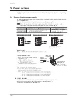
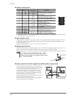
Connect the I/O signals to CN4 on the driver. Refer to p.16 for connection examples with a programmable controller.
Connecting the lead wire
Connect to insert the lead wire to the connector.
•
Applicable lead wire: AWG24 to 18 (0.2 to 0.75 mm
2
)
•
Length of the insulation cover which can be peeled: 10 mm (0.39 in.)
Crimp terminals can also be used to connect.
If crimp terminals are used, select the following terminals.
Manufacturer: PHOENIX CONTACT GmbH & Co. KG
Model
:
AI 0,25-10 [Conductor cross-sectional area: 0.14 to 0.34 mm
2
(AWG24)]
AI 0,34-10 [Conductor cross-sectional area: 0.14 to 0.34 mm
2
(AWG22)]
AI 0,5-10 [Conductor cross-sectional area: 0.40 to 0.65 mm
2
(AWG20)]
AI 0,75-10 [Conductor cross-sectional area: 0.65 to 0.82 mm
2
(AWG18)]
Connector model: DFMC1,5/6-ST-3,5
(
PHOENIX CONTACT GmbH & Co. KG
)
Summary of Contents for BMU5200A Series
Page 43: ...43...


