


Method of control via Modbus protocol
−12−
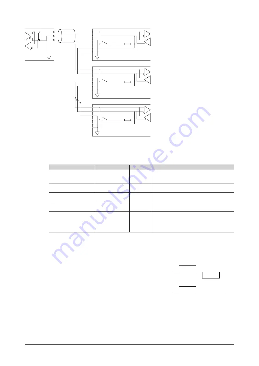
TR+
TR-
GND
TR+
TR-
GND
TR+
TR-
GND
TR+
TR-
GND
TR+
TR-
GND
120
Ω
0 V
∗3
0 V
SW2-No.7
Driver 1
Master device
RS-485
∗1
120
Ω
0 V
∗3
SW2-No.7
Driver 2
120
Ω
0 V
∗3
SW2-No.7
∗2
Driver 31
*1
Termination resistor 120
Ω
*2
Turn the termination resistor (SW2-No.7) ON.
*3
The GND line is used in common with the main
power supply input terminal (CN1) and control
power supply input terminal (TB1) [not insulated].
4.6 Setting of RS-485 communication
Set parameters required for RS-485 communication first.
Refer to p.28 when these parameters are set via communication.
Parameter name
Setting range
Initial value
Description
Communication parity
0: None
1: Even number
2: Odd number
1
Sets the parity for RS-485 communication.
Communication stop bit
0: 1 bit
1: 2 bits
0
Sets the stop bit for RS-485 communication.
Transmission waiting time
0 to 10000 (×0.1 ms)
100
Sets the transmission waiting time for RS-485
communication.
Communication timeout
0: Not monitored
0 to 10000 ms
0
Sets the condition in which a communication
timeout occurs in RS-485 communication.
Communication error alarm 1 to 10 times
3
Sets the condition in which a RS-485 communication
error alarm is generated.
A communication error alarm is generated when a
RS-485 communication error has occurred by the
number of times set here.
4.7 Communication mode
Modbus protocol communication is based on the single-master/multiple-slave method.
Under this protocol, messages are sent in one of two methods.
•
Unicast mode
The master sends a query to only one slave.
The slave executes the process and returns a response.
Query
Response
Master
Slave
•
Broadcast mode
If slave address 0 is specified on the master, the master can send a
query to all slaves. Each slave executes the process, but does not
return a response.
Master
Slave
No response
Query