4
•
Rear side of terminal cover
O-ring
Side view
•
To ensure safety, ground the motor using the
inside the terminal box.
•
Use a cable of the following specifications:
Applicable cable diameter:
∅
12 to 16 mm (
∅
0.47 to 0.63 in.)
Applicable lead wire: AWG18 (0.75 mm
2
) or more
•
When sealing the terminal cover, ensure that no scraps or particles get
caught between the contact surfaces.
•
This terminal cover is constructed to hold a O-ring. If this gasket comes
out of the cover, please reseal it correctly on the cover.
•
Refer to the tightening torque table to determine the appropriate tightening
torque to use when fastening the terminal cover and cable gland.
Loosening and then tightening the nut again may cause the nipple to
become loose. In this case, securely tighten the nipple again to the
applicable torque specified in the table below [unit: N·m (lb-in)].
Terminal cover (M3)
0.5 to 0.7 N·m (4.4 to 6.1 lb-in)
Cable gland (tightening nut)
2.0 to 2.5 N·m (17.7 to 22 lb-in)
Cable gland (nipple)
10 to 12 N·m (88 to 106 lb-in)
Protective Earth Terminal
1.0 to 1.3 N·m (8.8 to 11.5 lb-in)
Terminal block
0.8 to 1.0 N·m (7.0 to 8.8 lb-in)
Note
•
To make shielding function fully effective, use a cable of
an appropriate diameter.
•
Securely affix the cable exposed outside the motor so
that it does not receive stress.
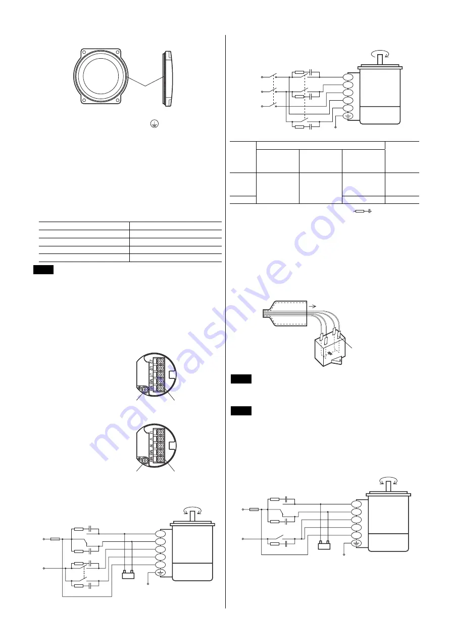
Wiring diagram
Connect the motor according to the figure. The direction of motor rotation is
as viewed from the side of the motor’s output shaft. The motor rotates in a
clockwise (CW) and counterclockwise (CCW) direction.
•
Layout of terminals
Single-phase motor
Terminal block
Protective Earth
Terminal
Three-phase motor
Terminal block
Protective Earth
Terminal
•
Wiring the single-phase motor
PE
CCW
CW
Motor
Electromagnetic
brake
MB
U2
Z2
MB
U1
Capacitor
SW1
ON
ON
SW2 CCW
CW
L
N
R
0
C
0
R
0
C
0
R
0
C
0
•
Wiring the three-phase motor
PE
CW
Motor
Electromagnetic
brake
MB
V
U
MB
W
SW1
L2 (S)
L3 (T)
L1 (R)
R
0
C
0
R
0
C
0
R
0
C
0
Input specification
Switch
No.
Single-phase
100 V/110 V/
115 V input
Single-phase
200 V/220 V/
230 V input
Three-phase
200 V/220 V/
230 V input
Note
SW1
250 VAC
1.5 A or more
Inductive load
Switched
simultane-
ously
SW2
125 VAC
3 A or more
Inductive load
250 VAC
1.5 A or more
Inductive load
−
−
In order to protect the relay contacts, a CR circuit (
) must be
connected. Refer to the wiring diagram.
R
0
=5 to 200
Ω
C
0
=0.1 to 0.2
µ
F 250 WV
Optional surge absorber is available (sold separately).
Model:
EPCR1201-2
Connecting the capacitor (single-phase motor only)
Capacitor terminals are internally electrically connection in twos; A-B and
C-D for easy connection. For easy to install terminals use187 series FASTON
terminals (TE Connectivity).
Use the supplied capacitor cap to insulate the capacitor terminal connection.
Capacitor cap
Capacitor
187 series tab
A
B
C
D
Note
For lead wire connection, use one lead wire for each
individual terminal.
Simplified connection
Note
Wiring cannot be simplified for vertical drive applications or
three-phase motors.
If the “RUN/STOP” operation of the motor and “RUN/STOP” operation of
the electromagnetic brake are controlled via a single switch (contact),
connect the lead wires as shown in the figure below.
Note that the motor’s magnetic energy affects the electromagnetic brake
windings, resulting in a longer braking time than that of the basic wiring by
approximately 50 ms and thus increased overruns.
PE
CCW
CW
Motor
Electromagnetic
brake
MB
U2
Z2
MB
U1
Capacitor
SW1
ON
SW2 CCW
CW
L
N
R
0
C
0
R
0
C
0
R
0
C
0


