background image


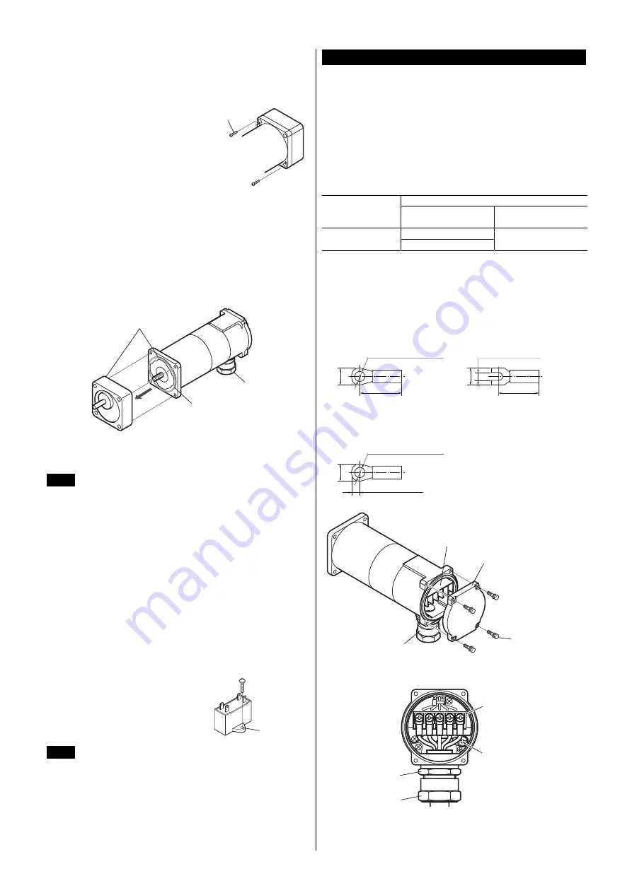
Installing/removing the gearhead 

The gearhead can be removed and the cable gland position changed to a 
desired 90° direction. The same procedure is followed when replacing the 
gearhead. 

1. 

Remove the hexagonal socket head 
screws (2 pcs.) assembling the motor 
and gearhead and detach the motor 
from the gearhead. 

Hexagonal socket

head screw

2. 

Using the pilot sections of the motor and gearhead as guides, install the 
gearhead to the motor. 
At this time, the cable gland position can be changed to a desired 90° 
direction. When installing the gearhead, slowly rotate it clockwise/ 
counterclockwise to prevent the pinion of the motor output shaft from 
contacting the side panel or gear of the gearhead. 
This flange surface is constructed to hold a O-ring. If this O-ring comes 
out of the flange groove, reseal it correctly on the flange groove. 
Also confirm that no gaps remain between the motor flange surface and 
the end face of the gearhead’s pilot section. 

Gearhead

Motor

Pilot

O-ring

Cable gland


After assembling the motor with the gearhead, install the motor/gearhead 
assembly using mounting screws by referring to the explanation under 
“Combination type”. 


Note 

• 

Do not forcibly assemble the motor and gearhead. Also, 
do not let metal objects or other foreign matters enter the 
gearhead. The pinion or gear of the motor output shaft 
may be damaged, resulting in noise or shorter service 
life. 

• 

Do not allow dust to attach to the pilot sections of the 
motor and gearhead. Grease may leak from inside the 
gearhead. 

• 

The hexagonal socket head screws used to assemble 
the motor and gearhead together only tentatively secure 
the two components. Always use the four supplied 
mounting screws when installing the motor/gearhead 
assembly. 


Pinion shaft type 

Pinion shaft type motors are used with a gearhead assembled. 
Refer to figure above. 


Mounting the capacitor (only for single-phase motors) 

Before mounting the provided capacitor, 
check that the capacitor’s capacitance 
matches that stated on the motor’s name 
plate. Mount the capacitor securely by using 
M4 screws (not provided). 

Ø4.3 mm

(Ø0.169 in.)


Note 

• 

Do not let the screw tightening torque exceed 1 N·m   
(8.8 lb-in) to prevent damage to the mounting foot. 

• 

Mount capacitor at least 10 cm (3.94 in.) away from the 
motor. If it is located closer, the life of the capacitor will 
be shortened. 


Connection 

Insulate all the wire connections, such as the connection between the motor 
and the capacitor connection. 
For safety’s sake, install a breaker or fuse in the power line. 
Ground the motor using a Protective Earth Terminal. 
The rotation direction is as viewed from the side of the motor’s output shaft. 
The motor rotates in a clockwise (CW) and counterclockwise (CCW) direction. 


Rotating direction of the gearhead output shaft 

The rotating direction of the gearhead output shaft may be opposite that of 
the motor shaft, depending on the gear ratio. Before performing wiring, be 
sure to check the rotating direction of the gearhead output shaft to be used 
and determine the desired direction of motor rotation. 


Gear ratio 

Gearhead model 

Same as the rotating 

direction of motor shaft 

Opposite the rotating 

direction of motor shaft

3 to 18


2GN S 

50 to 180 

25 to 36 

∗ 

The box ( ) of the model will be filled with the numeral to represent the 
gear reduction ratio. 


Connection method to a terminal box 

When connecting the cable (not supplied), use the following crimp terminal. 

• 

Applicable crimp terminal [unit: mm (in.)] 

For terminal block 

Insulated round terminal 

Ø3.6 (Ø0.142) or more

18 (0.71) or less

7.2 (0.283) or less

Insulated fork terminal 

3.6 (0.142) or more

18 (0.71) or less

6.4 (0.252) or less

For Protective Earth Terminal 

Insulated round terminal 

Ø4.1 (Ø0.161) or more

4.5 (0.177) or less

9 (0.354) or less

Terminal block

Terminal cover

Terminal cover

installation screw

(With spring washer)

Cable gland


• 

Layout of terminals 

Tightening nut

Nipple

Protective Earth

Terminal (M4)

Terminal block (M3.5)


Summary of Contents for World K Series

Page 1: ...ター丸シャフトタイプは マークを表示しています 電気用品安全法で要求される雑音電力および雑音端子電圧測定は ACラ インフィルタを接続して行なっています AC ラインフィルタは次の製品 または相当品を使用してください メーカー 三相 200 230 V Schaffner EMC FN251 8 07 TDK ラムダ株式会社 MC1310 RoHS 指令 RoHS 指令 2011 65 EU の規制値を超える物質は含有していません 安全上のご注意 ここに示した注意事項は 製品を安全に正しくお使いいただき お客様や 他の人々への危害や損傷を未然に防止するためのものです 内容をよく理 解してからお使いください ๔ この警告事項に反した取り扱いをすると 死亡または重傷 を負う場合がある内容を示しています ᵈᗧ この注意事項に反した取り扱いをすると 傷害を負うまた は物的損害が発生する場合がある内...

Page 2: ...切りシャフトタイプ 丸シャフトタイプ 品 名 モーター品名 コンデンサ品名 2RK6GN AW2MBJ 2RK6GN AW2MB CH45FAUL2 2RK6GN AW2MBU 2RK6GN AW2MB CH35FAUL2 2RK6GN CW2MBJ 2RK6GN CW2MB CH10BFAUL 2RK6GN CW2MBE 2RK6GN CW2MB CH08BFAUL 2IK6GN SW2MB 2IK6GN SW2MB 品名およびモーター品名は歯切りシャフトタイプです 丸シャフトタイプの 場合 品名およびモーター品名の GN は A になります 設 置 設置場所 風通しがよく 点検が容易な次のような場所に設置してください 屋内に設置された筐体内 換気口を設けてください 使用周囲温度 10 40 C 凍結しないこと 100 V 200 V 運転時は 10 50 C 使用周囲湿度 85 以下 ...

Page 3: ...取付ねじ 4 本 を使用してください 歯切りシャフトタイプ 歯切りシャフトタイプのモーターは ギヤヘッドを取り付けて使用します 上図を参考にしてください コンデンサの取り付け 単相モーターのみ 付属コンデンサの容量が モーター銘板に記載 されている容量と合っているか確認してくださ い M4 のねじ 付属していません を使用して 確実に取り付けてください Ø4 3 mm 重要 取付足の破損を防止するため コンデンサ取付用のねじは 1 N m 以下で締め付けてください コンデンサはモーターから 10 cm 以上離して取り付けてくださ い モーターの熱で コンデンサの寿命が短くなります 接 続 モーターと電源接続部 コンデンサ接続部など すべての接続部は絶縁処 理をしてください 安全のため ブレーカまたはヒューズを電源ラインに設置してください モーターは保護接地端子を使用して接地してください 回...

Page 4: ...C0 三相モーターの接続 PE CW 䊝䊷䉺䊷 㔚 䊑䊧䊷䉨 MB V U MB W SW1 L2䋨S䋩 L3䋨T䋩 L1䋨R䋩 R0 C0 R0 C0 R0 C0 スイッチの接点容量 スイッチ の番号 単相 100 V 110 V 115 V 入力 単相 200 V 220 V 230 V 入力 三相 200 V 220 V 230 V 入力 備 考 SW1 AC250 V 1 5 A 以上 誘導負荷 連動のこと SW2 AC125 V 3 A 以上 誘導負荷 AC250 V 1 5 A 以上 誘導負荷 接点の保護のため サージ電圧吸収用 CR 回路 を接続してくださ い 接続図を参照してください R0 5 200 Ω C0 0 1 0 2 µF 250 WV 当社でもオプション 別売 として用意しています 品 名 EPCR1201 2 コンデンサの接続 単相モーターのみ コンデンサには...

Page 5: ...なります 時間定格 インダクションモーター 連続運転が可能です 連続定格 レバーシブルモーター 連続運転可能時間は 30 分です 30 分定格 銘板に 30 min と記載されて います 拘束時の焼損保護 モーターは 出力軸が拘束されたときの焼損保護機能を備えています インピーダンスプロテクト方式 銘板に ZP と記載されています このモーターは 巻線インピーダンスを大 きくしています モーターが拘束されても電流 入力 の増加が抑えられ 内 部温度が一定の値以上にならないように設計されています 故障の診断と処置 モーターの運転操作が正常に行なえないときには この項をご覧になり 適 切な処置を行なってください それでも正常に運転できないときは 最寄り のお客様ご相談センターにお問い合わせください 現 象 確認内容 モーターが回転 しない モーターが低速 で回転する 電源電圧を確認してください...

Page 6: ... および装置の利用 に関して産業財産権上の問題が生じても 当社は一切の責任を負い ません 製品の性能 仕様および外観は改良のため予告なく変更することがあ りますのでご了承ください 取扱説明書には正確な情報を記載するよう努めていますが 万一ご 不審な点や誤り 記載もれなどにお気づきの点がありましたら 最寄り のお客様ご相談センターまでご連絡ください は 日本その他の国におけるオリエンタルモーター 株式会社の登録商標または商標です Copyright ORIENTAL MOTOR CO LTD 2010 2018 年 1 月制作 ...

Page 7: ...ction values of RoHS Directive 2011 65 EU Safety precautions The precautions described below are intended to prevent danger or injury to the user and other personnel through safe correct use of the product Use the product only after carefully reading and fully understanding these instructions Warning Handling the product without observing the instructions that accompany a Warning symbol may result...

Page 8: ...CH10BFAUL 2RK6GN CW2MBE 2RK6GN CW2MB CH08BFAUL 2IK6GN SW2MB 2IK6GN SW2MB The list above shows pinion shaft motors For the round shaft motor GN in the model and motor model are replaced by A Installation Location for installation Install it in a well ventilated location that provides easy access for inspection The location must also satisfy the following conditions Inside an enclosure that is insta...

Page 9: ...nly for single phase motors Before mounting the provided capacitor check that the capacitor s capacitance matches that stated on the motor s name plate Mount the capacitor securely by using M4 screws not provided Ø4 3 mm Ø0 169 in Note Do not let the screw tightening torque exceed 1 N m 8 8 lb in to prevent damage to the mounting foot Mount capacitor at least 10 cm 3 94 in away from the motor If i...

Page 10: ...lock Protective Earth Terminal Wiring the single phase motor PE CCW CW Motor Electromagnetic brake MB U2 Z2 MB U1 Capacitor SW1 ON ON SW2 CCW CW L N R0 C0 R0 C0 R0 C0 Wiring the three phase motor PE CW Motor Electromagnetic brake MB V U MB W SW1 L2 S L3 T L1 R R0 C0 R0 C0 R0 C0 Input specification Switch No Single phase 100 V 110 V 115 V input Single phase 200 V 220 V 230 V input Three phase 200 V...

Page 11: ...Time rating Induction motors Induction motors have a continuous rating Reversible motors Reversible motors have a 30 minutes rating 30 min is indicated on the nameplate Locked rotor burnout protection The motor is equipped a function of overheat protection for when the motor output shaft is locked Impedance protection ZP is stamped on the motor nameplate The motor has higher coil impedance When th...

Page 12: ...n January 2018 Technical Support Tel 800 468 3982 8 30 A M to 5 00 P M P S T M F 7 30 A M to 5 00 P M C S T M F www orientalmotor com Schiessstraße 44 40549 Düsseldorf Germany Technical Support Tel 00 800 22 55 66 22 www orientalmotor de Tel 01256 347090 www oriental motor co uk Tel 01 47 86 97 50 www orientalmotor fr Tel 02 93906346 www orientalmotor it Tel 55 11 3266 6018 www orientalmotor com b...

Reviews: