27
■
C.OFF (current-off ) input
This input is used to adjust the position by
manually moving the motor’s output shaft from the
load side.
1.
When the C.OFF input is turned to “ ON ”, the
driver cuts off the current supply to the motor
and the motor loses its holding torque. In this
condition, the position of the output shaft can be
adjusted manually.
2.
When the C.OFF input is turned to “ OFF ”, the
driver resumes the current supply to the driver
and restores the motor’s holding torque.
■
Output signals
All driver output signals are photocoupler/open-
collector outputs.
The signal state indicates the “ ON: current
supplied ” or “ OFF: current not supplied ” status of
the internal photocoupler or transistor rather than
the voltage level of the signal.
R
2
TIMING
7
8
V
0
10 mA or less
+
-
Controller output
Driver internal circuits
0V
Use an output signal voltage of 5 VDC minimum
and 24 VDC maximum, and use an output signal
current of 10 mA max.
If the output signal current is greater than 10 mA,
connect an external resistor R
2
.
V
0
R
2
= [
Ω
]
10 mA
●
Do not turn the C.OFF input to ON while the
motor is operating. If the input is turned ON, the
motor will stop and lose its holding capability. A
load may descend, resulting in injury or
equipment damage.
Warning
●
If the motor’s output shaft must be moved
directly by hand (for manual alignment, etc.), do
so after confirming that the driver’s C.OFF
(current-off ) input is ON. Failure to do so may
result in injury.
Caution
When operating the motor, always keep the
C.OFF input in the “ OFF ” state.
NOTE
●
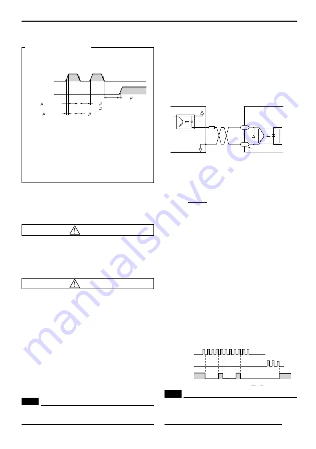
Input pulse signals having a waveform with
sharp rise/ fall edges, as shown below.
ON
OFF
ON
OFF
CW input
2 s or less
2 s or less
90%
10%
CCW input
Pulse duty
50% or less
5 s or more
50 s or more
100 s or more
ON: 4.5 to 5 V
OFF: 0 to 1 V
(25 s or more)
Pulse signal waveform
●
The shaded area indicates when the photocoupler
diode is ON. The motor moves when the
photocoupler state changes from ON to OFF.
●
The interval period of 100
µ
s or more when
switching from CW to CCW is only a reference.
The exact interval varies significantly depending on
the motor and load inertia.
●
The figures in parentheses ( ) are specifications
for the driver
CSD2120P2
,
CSD2130P
,
CSD2140P
,
CSD2145P
.
●
TIMING (excitation timing) output
1.
The TIMING (excitation timing) signal indicates
that the excitation of the motor is in the initial
state (STEP 0). Use this signal to detect the
home position accurately by matching the
mechanical home position of the device and the
excitation home position (STEP 0) of the motor.
2.
The signal is output once each time the
excitation sequence returns to (STEP 0) in
synchronization with input pulses. The
excitation sequence is designed to complete
one cycle as the motor shaft rotates 7.2°.
Output is as follows:
Full step: 1 output per 4 pulses
Half step: 1 output per 8 pulses
(Step)
CW input
CCW input
Timing
output
1 2 3 4 5 6 7 8 9 1011
1 2
0 1 2 3 0 1 2 3 0 1 2 3
3 2 1 0
3
When the power is turned ON, the excitation
sequence is reset to STEP 0 and the timing lamp
light up.
NOTE
Timing chart at 1.8°/step
●
When used as indicated in the sample connection, the
signal is in the “photocoupler ON” state at STEP 0.


