9 Clamping wedge and mandrel assembly BRB 4
Operating instructions BRB
50
(08.10)
MT_BRB_BA_04_790086762_00.doc
orbitalum tools
gmbh
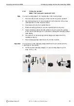
9.3.3
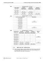
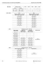
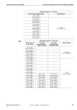
Replacing the clamping wedges:
BRB 4 "NC" with mandrel Ø 34.50 and
BRB 4 "NC" Auto with mandrel Ø 34.50
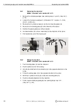
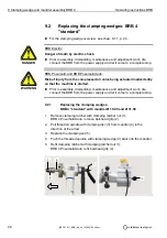
1. The machine housing (1) should be positioned on the mandrel so that
dimension "X" is approx. 50 mm (1.969 inches).
2. BRB 4 Pneumatic and Electric, rotate clamping nut (2) in the direction of
the arrow as far as the stop.
3. BRB 4 Pneumatic/Auto version, insert the piston rod (3) from the clamping
cylinder (4) in the direction of the arrow as far as the stop. The piston rod
is inserted when only approx. 12 mm (0.472 inch) protrudes from the
cylinder in the unclamped position, see chap. 10.1.3, p. 61.
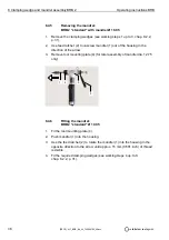
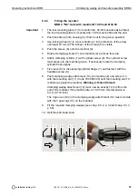
4. Remove stopper (5) with size 24 open-end wrench.
BRB 4 Electric "NC"
BRB 4 Pneumatic/Auto "NC"
Piston rod in BRB 4 Pneumatic/Auto
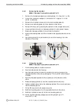
5. The 3 clamping wedges (6) can now be pushed out of the clamping wedge
attachment guide (7) in the direction of the arrow.
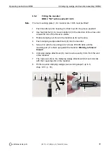
6. Insert selected clamping wedges into the clamping wedge attachment
guide (7).
Tool damage!
The clamping wedges must not be tilted.
Ensure that the 3 clamping wedges used are always identical.
7. Refit stopper (5) with size 24 open-end wrench.
ATTENTION
7
6
5
8
7
x
5
1
2
x
1
4
5
3

