IOM MANUAL
SA ALUMINUM STOP LOG
www.orbinox.com
EDITION 12/2017
IOM-SA
4.
INSTALLATION
This section describes the different installation methods (See section 4.1 to 4.3). Please refer to the GAD to identify
the installation method that is applicable to the purchased equipment.
The concrete construction shall be flat, level and plumb, and shall be in accordance to DIN 18202 or equivalent
ACI 117-06 standard (see Section 9). If necessary, use non-shrink grout in order to meet the specified standard.
The minimum concrete strength shall be 25 MPa (3,600 PSI).
The following procedures are general installation guidelines. Please refer to the notes on the GAD for specific
information about the installation method and the required materials (type, size and quantity of anchor bolts,
construction sealant, etc.). Always follow the anchor bolt and construction sealant manufacturers’ installation
instructions. Note that, typically, construction sealant requires dry concrete surfaces for its application.
Note that as standard, installation materials such as anchor bolts, hex-bolts and construction sealant are not
supplied with the equipment, unless otherwise specified.
4.1.
EMBEDDED IN CONCRETE (IN THE CHANNEL RECESS)
Step 1: Initial assessment
Check that the concrete wall meets the requirements described in Section 4.
Verify that all installation materials specified on the GAD are available. Wooden wedges are used to center and
level the gate in the recess prior to embedding it in concrete.
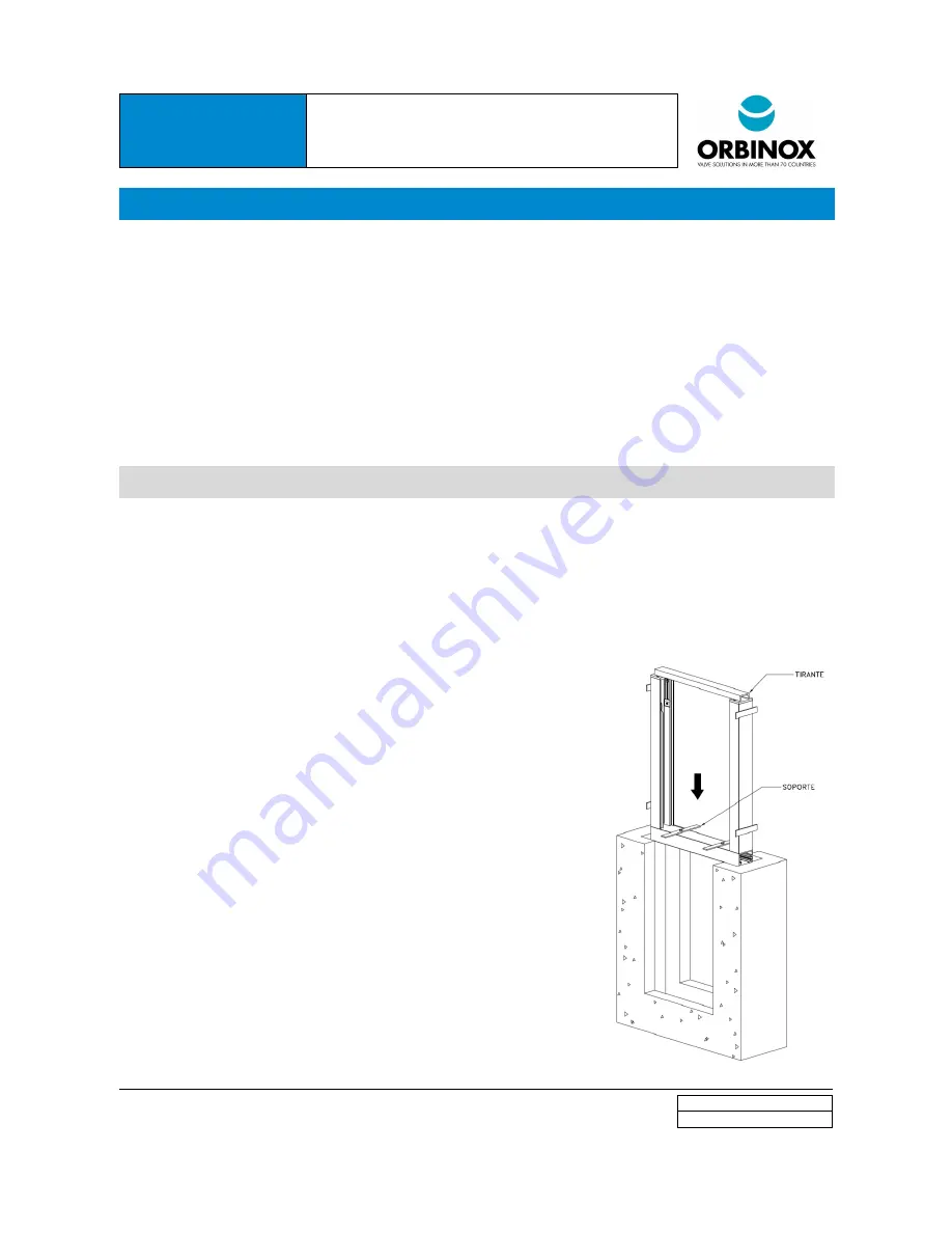
Step 2: Frame alignment in the recess
Position and center the unit in the recess of the wall, using wooden wedges.
Align the unit vertically and make sure that the frame is flush with the invert
of the channel. The frame includes two threaded holes, which must be used to
secure vertical alignment supports (see
Figure 3
). Note that the supports are
not supplied, unless otherwise specified (two metal or wooden plates are
required).
Align the unit horizontally and make sure that the Frame Guide is flush with
the channel side wall. Additionally, make sure that the gate is perpendicular
to the side walls of the channel (See
Figure
3). For aluminum frames, use
wooden wedges to center the unit in the recess. As an option, stainless steel
frames include “Lateral Centering Fittings”. In that case, adjust the hex bolts
for centering the frame.
Step 3: Frame embedment in the wall recess
Pour the second phase of concrete. Take special care not to damage the
seals (see
Figure 4
).
Do not pour in more than one meter concrete columns to avoid damage to
the frame.
Remove the frame tensioning top beam if applicable.
Figure 2


