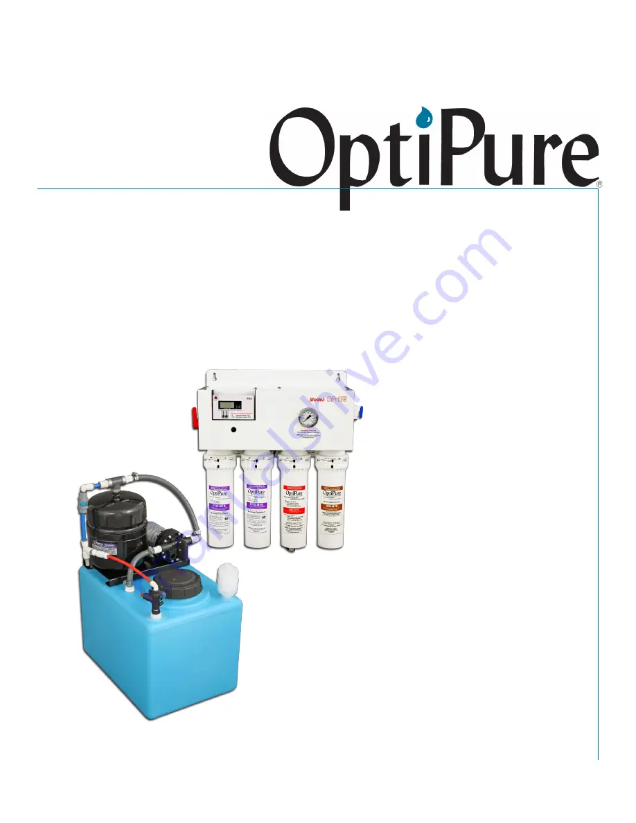
OptiPure OP175 Installation, Operation & Maintenance Manual Download Page 1

OP175 

Advanced Membrane 

Separation System

Installation, Operation 

& Maintenance Manual

Rev. 1

Manufactured By:

OptiPure Div. of 

Procam Controls, Inc.

2605 Technology Drive, Bldg. 300

Plano, TX 75074

P: 972.881.9797   F: 972.422.6262

OP175_manual_v1.indd

©2010 Procam Controls, Inc. All Rights Reserved

Summary of Contents for OP175

Page 1: ...Installation Operation Maintenance Manual Rev 1 Manufactured By OptiPure Div of Procam Controls Inc 2605 Technology Drive Bldg 300 Plano TX 75074 P 972 881 9797 F 972 422 6262 OP175_manual_v1 indd 201...

Page 2: ...gree II 7 Indoor use only protect from elements Explanation of Symbols The following symbols are used on the water processor The symbols and their explanation is given below Earth ground WARNING Hazar...

Page 3: ...rating Pressure Gauge Membrane Reject Water Tubing Connection AMS QT15 Membrane Cartridge Reject Water Outlet 1 4 Push to Connect Connect to drain per local regulations 1 2 3 4 Optimized Water to Stor...

Page 4: ...ted within 5 feet of the location of the unit Drain must allow a minimum flow of 2 gallons per minute Compliance with most local plumbing codes requires installation of an approved air gap in the drai...

Page 5: ...Gauge Membrane Reject Water Tubing Connection AMS QT15 Membrane Cartridge Water Quality Monitor Optimized Water to Storage Tank Inlet on Valve Repressurization Assembly Outlet Hose Barb Repressur izat...

Page 6: ...mp until completing the following section System Start Up Refer to Typical Installation diagram on page 5 and How to Use Our Quick Connect Fittings on page 16 when making the following connections A f...

Page 7: ...nsions IMPORTANT ALLOW A MINIMUM OF 24 IN FRONT OF THE PROCESSOR FOR MAINTENANCE AND SERVICE DO NOT MOUNT SYSTEM ABOVE THE CEILING OR IN A LOCATION THAT IS NOT EASILY ACCESSIBLE WHEN THE 16 GAL TANK A...

Page 8: ...e connection between the 1 2 hose and distribution line but for now leave the line loose and route the loose end of the gray hose into a drain or bucket make certain the hose length will reach the sto...

Page 9: ...ump will run more smoothly and the water flow from the gray hose will become steady 4 Unplug the RP Pump cord Connect to Equipment You are almost ready to enjoy the benefits of Optimized Water All tha...

Page 10: ...on to drain The pure water stream continues through the Permeate Check Valve 8 and through the Mineral Addition cartridge 2 then on to the tank through the Tank Inlet Divert Valve 11 on top of the St...

Page 11: ...the ability to measure membrane production by closing the Buffer Tank Valve 17 and turning the Tank Inlet Divert Valve 11 to the bypass or UP position This diverts the permeate pure water produced by...

Page 12: ...lve PN 524 20010 Pressure Gauge PN 530 20018 Reject Flow Control PN 564 02105 OUT Permeate Conductivity Probe Pressurized Water Check Valve PN 524 01035 Sample Port Valve PN 520 12223 Permeate Check V...

Page 13: ...ge Tank PN 570 00016 Air Breather PN 300 40005 RP Pump PN 704 35513 Tank Bracket PN 594 80516 Buffer Tank PN 340 50001 Buffer Tank Valve PN 520 14501 Optimized Water Inlet Connect line from Optimized...

Page 14: ...d pushing up then turn a quarter turn to the right 5 If it is necessary to replace the Mineral Addition Cartridge repeat steps 4 5 for the Mineral Addition Cartridge 6 Install a piece of 3 8 tubing in...

Page 15: ...rt valve open the Sample Port and direct to a bucket or drain Turn the Tank Inlet Divert Valve to the Bypass or UP position Open the Water Supply Valve and put the Emergency Bypass Valve in the SERVIC...

Page 16: ...Push tubing straight in Resistance will be felt when the tubing meets the O ring The outside of the tubing must be free of knicks and gouges Cut tubing with a plastic tubing cutter or a razor knife Ma...

Reviews: