


Version 2.1.1 - 2020-07-27
65
Originalbetriebsanleitung
B40 GSP
DE | EN
B40G
SP_
part
s
.f
m
7.16
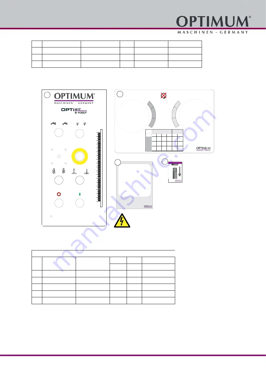
Maschinenschilder - Machine labels
Abb.7-13: Maschinenschilder - Machine labels
7
Platte
Plate
1
030031712019
8
Alu- Profil
Aluminium profile
1
0302130381
9
Bohrfutterschutz kpl.
Drill chuck protection cpl.
1
03334403170
10
Schraube
Screw
2
GB819-85/M5x8
D
D
0
10
20
30
40
50
60
70
80
90
100
110
120
130
140
150
160
170
180
optimum-maschinen.de
Master Labels
1
Master Labels
8
E
D
F
B
A
C
1
2
1
2
1
2
D
50 100 125 250 345 690
E
75
150 180 365 500 1015
F
110
215 260 520 725 1450
A
B
C
A
B
C
D
E
F
Master Labels
2
Master Labels
Hauptschalter
Main switch
Master Labels
9
B40 GSP - Maschinenschilder - Machine labels
Pos.
Bezeichnung
Designation
Menge
Grösse
Artikelnummer
Quantity
Size
Article no.
1
Frontschild
Front label
1
2
Getriebeschild
Gear box label
1
4
Hinweisschild
Instruction label
1
03334400199
8
Hinweisschild
Instruction label
1
9
Schild Hauptschalter
Main switch label
1