Version 1.0 - 2020-12-22
109
Translation of original instruction
TU2506VB
EN
T
U
2506V
B_GB
_3.
fm
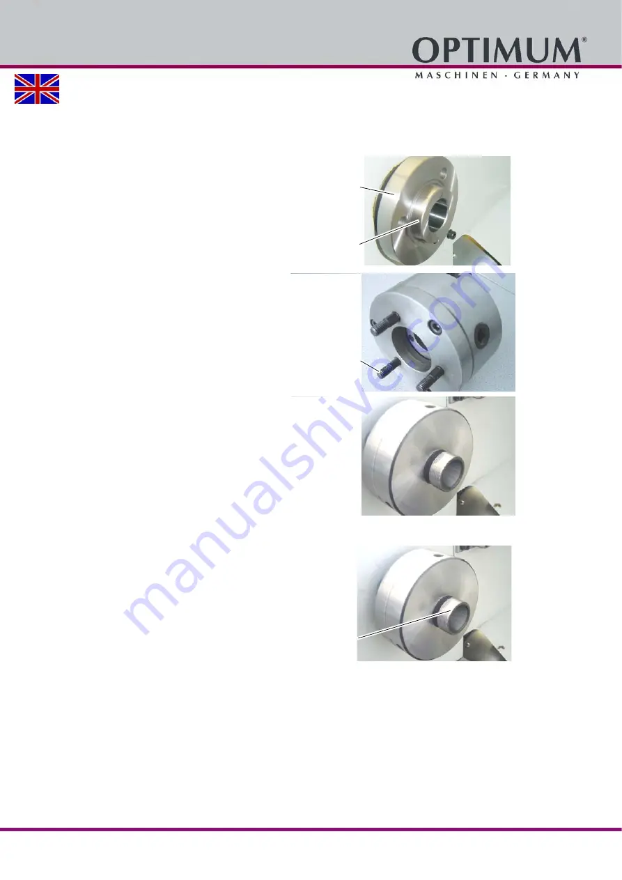
3.10.3 Collet chuck assembly instruction
Mounting the collet chuck 3441305 on your lathe.
Proceed as follows.
Before dismantling, mark the position
of the lathe chuck on the spindle
flange with e.g. a felt pen. This ena-
bles an identical reassembly.
Disassemble the lathe chuck.
Clean all surfaces of the spindle nose
and collet chuck extremely thoroughly.
Remove the grub screws from the
lathe chuck and screw the grub screws
into the collet chuck.
Measure the runout of the spindle
flange. Mark the largest positive
deflection of the dial gauge on the
spindle flange with a felt pen.
Attach the collet chuck to the spindle
flange, tighten the nuts slightly.
Tighten the nuts gradually and evenly
alternately at least three times in a row
(this is the only way to achieve the
best concentricity).
Measure the run-out of the collet chuck
in the taper surface.
Position the collet chuck by turning
each 120° on the spindle flange until
the highest concentricity is achieved.
Mark the position of the highest con-
centricity of spindle flange with collet
chuck and then mount the collet chuck
in this best position.
Img.3-4:
Collet chuck 3441305 shown without union nut.
Spindle flange
(Short tapered seat)
Measuring position
Grub screw
Measuring posi-
tion


