background image

280ES / 420ES / 650ES / 1000ES / 1400ES

35

6.3 Battery Replacement Procedure for 1000ES / 1400ES

Changing the batteries in your 

OPTI-UPS™

 is a safe and easy procedure. Since the

battery is isolated from the AC input you may leave your UPS and computer or other
equipment on during the following procedure. Please note that if you choose to leave the
UPS on when the battery is removed, it will not be able to power your equipment if a
power failure occurs. Please read the cautions in section 6.1 before performing the
following steps.

1. 

Remove the two small screws from the bottom of the front panel.

2. 

Gently slide the front panel off.

3. 

Remove the battery retaining plate by loosening the six screws holding it in place.

4. 

Gently pull out the battery by the tape attached to it.

5. 

Disconnect the two wires connecting the battery to the UPS.

6. 

Connect the wires to the new battery, making sure that the red wire is connected to
the red battery terminal and the black wire is connected to the black battery terminal.

7. 

Push the new battery into place.

8. 

Reposition the battery retaining plate and tighten the six screws.

9. 

Slide the front panel back into place.

10.

  Tighten the two small screws on the bottom of the front panel.

A

B

C

PULL HERE

PULL HERE

Summary of Contents for 1000ES

Page 1: ...User s Guide POWER ENHANCED SERIES Models 280ES 420ES 650ES 1000ES 1400ES...

Page 2: ...OPTI UPS Corporation For your records The serial number of your UPS is on the rear panel You should note the serial number in the space provided below Retain this booklet as a permanent record of your...

Page 3: ...us United States or Canada contact your dealer for warranty information Who the warranty protects This warranty is valid only for the first consumer purchaser What the warranty does not cover 1 Any pr...

Page 4: ...R OTHER COMMERCIAL LOSS EVEN IF ADVISED OF THE POSSIBILITY OF SUCH DAMAGES 2 ANY OTHER DAMAGES WHETHER INCIDENTAL CONSEQUENTIAL OR OTHERWISE 3 ANY CLAIM AGAINST THE CUSTOMER BY ANY OTHER PARTY Effect...

Page 5: ...s 2 5 Site Wiring Fault Indicator 16 2 6 User Configurable Settings 16 2 7 Communication Port and Pin Assignments 17 2 8 Data Line Surge Suppression 18 3 INSTALLATION AND OPERATION 3 1 Unpacking and I...

Page 6: ...2 280ES 420ES 650ES 1000ES 1400ES 6 3 Battery Replacement Procedure for 1000ES 1400ES 30...

Page 7: ...IONS IMPORTANTES CONCERNANT LA S CURITE POUR LE REMPLACEMENT UTILISER LE M ME NOMBRE DE BATTERIES DU MOD LE SUIVANT 280ES 1 7AH 12V 420ES 1 7AH 12V 650ES 1 12AH 12V 1000ES 2 12AH 12V 1400ES 2 12AH 12V...

Page 8: ...xcept a 2 pole 3 wire grounded receptacle Do not place the UPS near water or in environments of excessive humidity Do not allow liquid or any foreign objects to get inside the UPS Do not block air ven...

Page 9: ...icht in der N he von Wasser oder in Umgebungen berm iger Feuchtigkeit aufstellen Fl ssigkeiten oder Fremdobjekte d rfen nicht in das Innere der UPS dringen Lufteinfuhr an der Vorderseite und Luftaustr...

Page 10: ...jamais mettre I UPS pr s de l eau ou dans un milieu trop humide Ne jamais faire entrer du liquide ou d objet tranger dans I UPS Ne jamais boucher les ventilations d air de I UPS ou l a ration arri re...

Page 11: ...ease the separation between the equipment and the receiver Connect the equipment into an outlet on a circuit different from that to which the receiver is connected Consult the dealer or an experienced...

Page 12: ...s transients and blackouts from reaching your sensitive equipment Your equipment may include such items as computers and computerized instruments to telecommunication systems When AC power is present...

Page 13: ...280ES 420ES 650ES 1000ES 1400ES 9...

Page 14: ...eceives the normal rated voltage If the voltage fluctuates down by 15V the boost function automatically steps it back up This provides your equipment with excellent voltage regulation and less possibi...

Page 15: ...improperly wired AC power outlet see Section 2 5 This feature warns you if the ground wire is missing if the input line and neutral wires are reversed or if the neutral wire is overloaded This alerts...

Page 16: ...or more information and Section 4 2 for the dimensions of all models MODEL 280ES 420ES 650ES 100 110 120V Version Test Silence Test Silence Button Status LED On Off Button Data Line Surge Suppression...

Page 17: ...650ES 1000ES 1400ES 13 MODEL 280ES 420ES 650ES 220 230 240V Version Test Silence Status LED IEC 320 Inlet DIP Switch Communication Port Outlets Fuse Test Silence Button On Off Button Data Line Surge...

Page 18: ...1000ES 1400ES MODEL 1000ES 1400ES Communication Port Outlets Site Wiring Fault Indicator Circuit Breaker 100 110 120Version Test Silence Button On Off Button Status LED Date Line Surge Suppression Dip...

Page 19: ...0ES 420ES 650ES 1000ES 1400ES 15 MODEL 1000ES 1400ES Test Silence Button On Off Button Status LED 220 230 240Version Communication Port Date Line Surge Suppression Outlets Dip Switch IEC 320 Inlet Fus...

Page 20: ...UPS once in a while to verify that the batteries are in good condition If you press the Test Silence Button when AC power is available the UPS will test itself by switching to its internal battery for...

Page 21: ...urge protection Battery Mode When this LED is lit the UPS is providing power from its battery Also this LED is lit when you press the Test Silence Button to test the battery see Section 2 3 After the...

Page 22: ...is lit the UPS is correcting an overvoltage The UPS lowers the output voltage approximately 12 lower than the input voltage without using any battery power Battery Mode When this LED is lit the UPS i...

Page 23: ...table on the following page Two of the adjustable parameters are low and high voltage transfer points A transfer point is the predetermined voltage at which the UPS transfers to battery power On the 1...

Page 24: ...too much equipment to the UPS during the startup on battery operation Function Switch Setting Operation Nominal Voltage Dip1 off Dip2 off Default factory setting Dip1 on Dip2 on 100V 220V Dip1 on Dip2...

Page 25: ...pplication The major functions of this type of software normally include the following To broadcast a warning when power fails To close any open files before the battery reserves are exhausted To turn...

Page 26: ...o ground 2 8 Data Line Surge Suppression The data line surge suppression on the rear panel provides an easy way to protect a network RJ45 or modem RJ11 connection from hazardous spikes Connect your 10...

Page 27: ...Placement 1 This unit is intended for indoor use only Although your UPS is very rugged its internal components are not sealed from the environment 2 The UPS must be installed in a protected environme...

Page 28: ...and current of each piece of equipment VA requirements for example 120V x 2 7A 324VA 120V x 2 0A 240VA Add up the VA requirements for each device for example 324VA 240VA 564VA 4 Make sure that your UP...

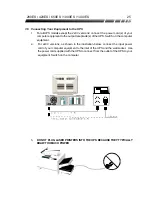
Page 29: ...f the UPS Switch on the computer equipment 2 For 2x0V versions as shown in the illustration below connect the input power cord of your computer equipment to the inlet of the UPS and the wall socket Us...

Page 30: ...perates properly and without interruption If you leave your UPS on continuously it is a good idea to perform a backup function test at least once a month You can configure OPTI SAFE to automatically p...

Page 31: ...60 220 230 240 2 95 2 83 2 71 1000ES 50 60 100 110 120 10 0 9 1 8 3 50 60 220 230 240 4 5 4 3 4 2 1400ES 50 60 100 110 120 14 0 12 7 11 7 50 60 220 230 240 6 4 6 1 5 8 Input Output Voltage AC Line Vol...

Page 32: ...220 230 240 300V 6500A 560 1000ES 1400ES 100 110 120 175V 6500A 475 1000ES 1400ES 220 230 240 300V 6500A 840 Data Line Surge Suppression Telephone Line Surge Protection 6KV Peak 1 2 S 50 Waveform 10...

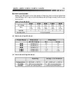
Page 33: ...24V Type 12V 7AH 12V 7AH 12V 12AH 12V 12AH 12V 12AH Quantity 1 1 1 2 2 Recharge time 4 hours typical 4 2 Mechanical Specifications Product Name Dimensions Weight Kg W D H mm Net Gross 280ES 120x345x1...

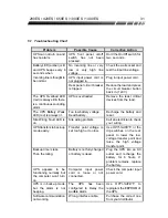
Page 34: ...ies that you may encounter under normal working conditions If the UPS fails to operate properly please review the following steps before calling the repair center 1 Is the UPS plugged into a proper wo...

Page 35: ...Too low battery voltage Dead battery Recharge the battery and reset Site Wiring Fault LED is on Site wiring problem Call an electrician to check your wiring UPS transfers to back up mode easily Trans...

Page 36: ...port of the computer has not been configured properly Check to see that the serial port is enabled in the CMOS settings Also check for IRQ conflicts and make sure the settings match those of OPTI SAF...

Page 37: ...eep unknowledgeable i e unauthorized personnel away from the batteries CAUTION Except for the battery the unit contains no user serviceable parts Repairs should be performed only by factory trained se...

Page 38: ...e occurs Please read the cautions in section 6 1 before performing the following steps 1 Remove the three small screws from the bottom of the UPS plastic case 2 Gently slide the battery plate off 3 Ge...

Page 39: ...steps 1 Remove the two small screws from the bottom of the front panel 2 Gently slide the front panel off 3 Remove the battery retaining plate by loosening the six screws holding it in place 4 Gently...

Reviews: