Supply power to the sensor.
After warm-up for approx. 30sec.,
this product becomes the stand-by state.
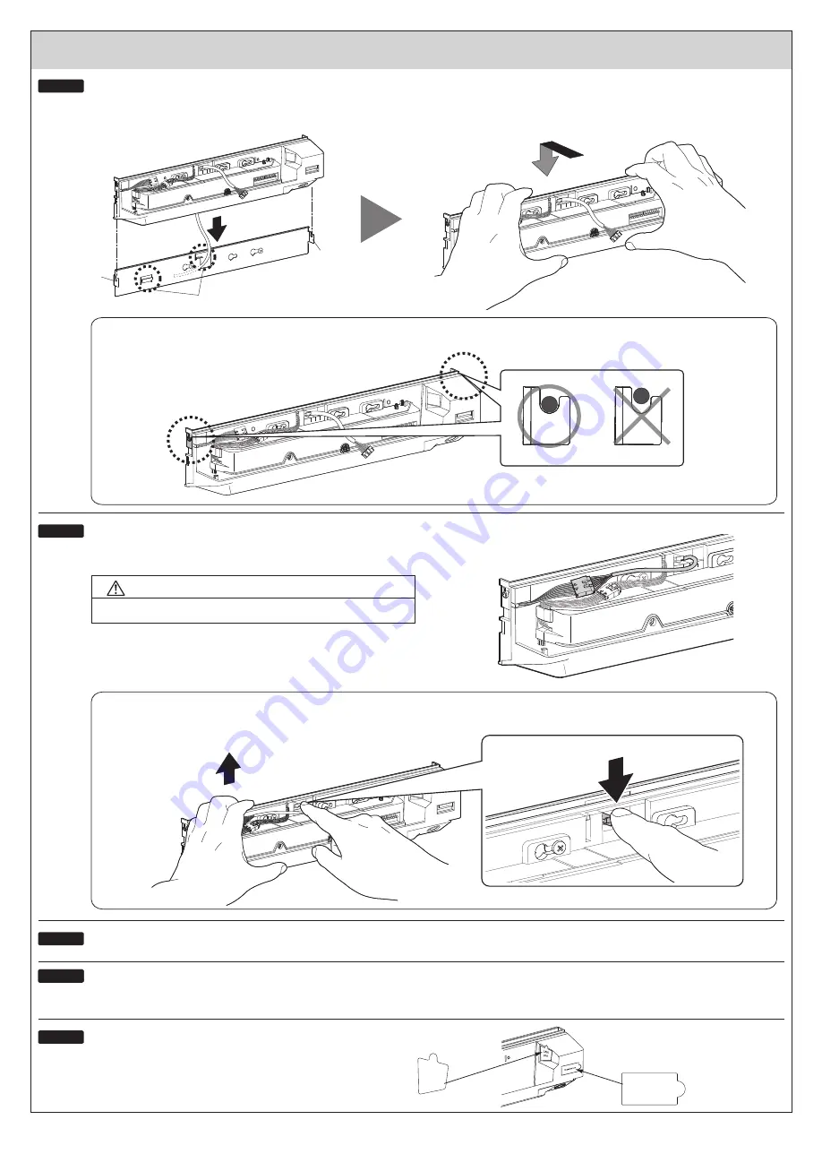
When detaching this product from the mounting plate, raise the sensor upward while pushing down the removing pawl as shown below.
Confirm that the protruded parts of this product are fully lowered and fixed on the both sides of claws of the mounting plate.
Connect the wiring connector and the power/output connector.
Fix the main body to the mounting plate.
Installation
Raise it upward.
- 4 -
Hook
Hook
Fitting section
Perform fitting and pull down while pressing the main body to the mounting
plate.
Put the main body on the hook of the mounting plate.
STEP 9
STEP 10
■
Make sure that the connectors are properly connected.
STEP 11
STEP 12
Adjust the image recognition area and set the dipswitches.
(Refer to
Web setting manual
.)
For the header sensor, refer to the operation manual of the header sensor.
STEP 11
STEP 13
Dipswitches
LAN
port
For the
dust proof, affix
the attached protection seals to
the openings section of this product.
Push down the removing pawl.
Danger of fire and electric shock
WARNING


