Opitec 101.887 Instruction Manual Download Page 3

3

E101887#1


3. Tools:


Wood files / rasps:


Choose the correct grade of  file or rasp according to the work in hand.


Use needle files for small slots and notches


Note! 

Use a sand paper and block on all flat surfaces and loose sheet  


on curves.


Sanding:


Use a sand paper and block on all flat surfaces and loose sheet on curves;


Drilling:


Use a pillar drill


Note! 

Take care to adhere to the safety rules, tie all long hair back,  


remove jewellery, wear an apron and safety glasses. Hold the work 


to be drilled in a machine vice.


Clamping:


Hold the work with clamps whilst the glue is drying. Do not over tighten them


or they may leave marks.


Soldering:

  Use a 30 Watt soldering iron.


  Clean the area to be soldered and use a flux. 


  Please Note! 

Soldering iron tips get hot and can cause burns.!
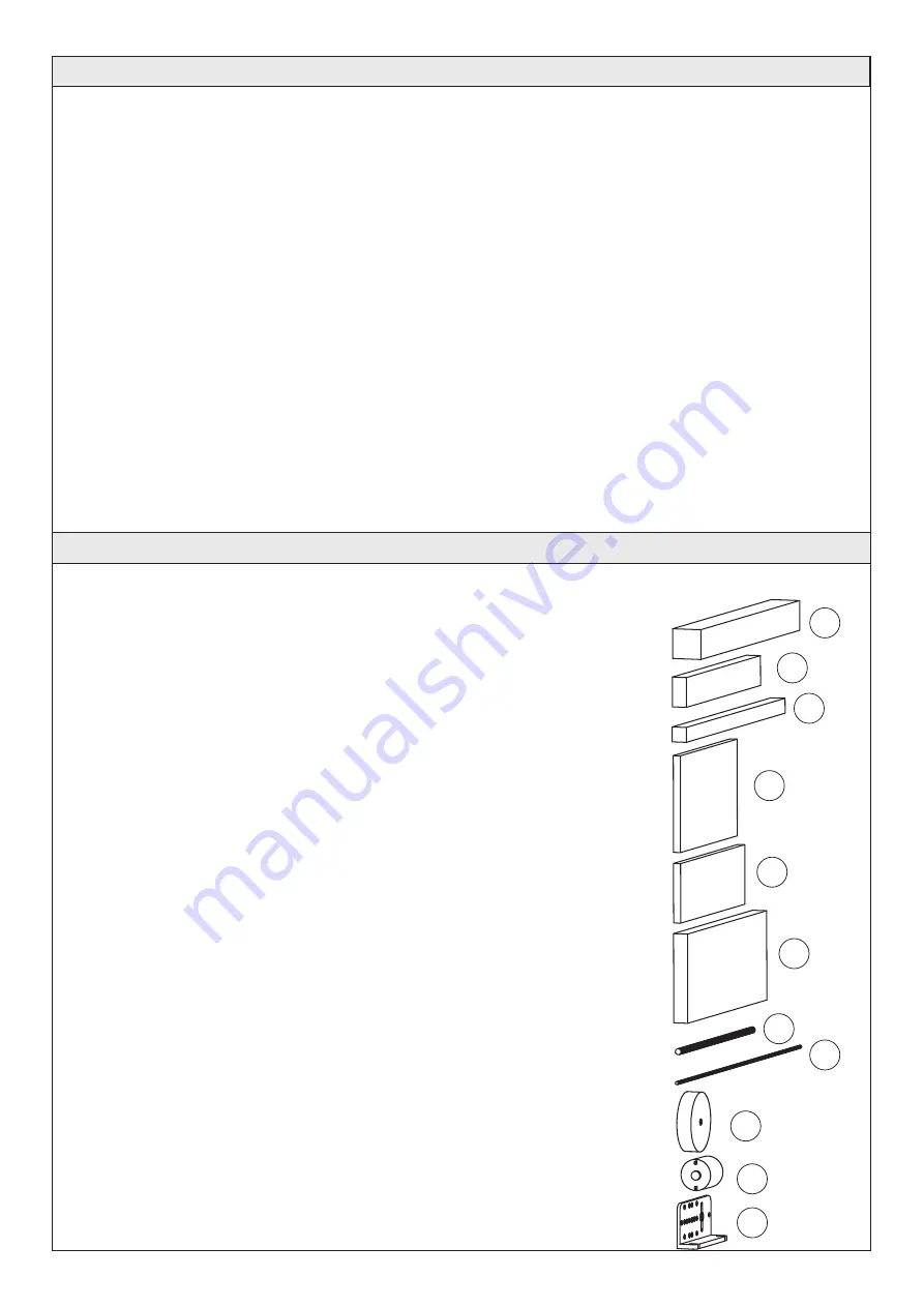
  4. Parts List:
  Part 

Material 

Amount 

Size 

Diagram

  Chassis


Pine 

20 x 20 x 200 mm

  Seat / Arms/

  Body / Head 


Pine 

10 x 20 x 150 mm

  Arms /Legs 


Pine 

10 x 10 x 200 mm


Base  

Plywood 

5 x 65 x 115 mm


Seat  

Plywood 

5 x 40 x 130 mm


Controller/


Battery holder  

Plywood 

10 x 60 x 160 mm


Axle/ Neck/


Steering bar


Beech dowel 

4mm dia x 150mm


Roof supports


Welding rod 

3  2 mm dia x 250mm


Wheels


Beech 

40mm dia


Motor


21 dia x 25mm


Angle brackets


Plastic 

2

3

4

5

6

7

8

9

10

11

1

Summary of Contents for 101.887

Page 1: ...ay toys for young children They are teaching aids for young people learning the skills of Craft Design and Technolo gy These projects should only be underta ken and tested with the guidance of a fully...

Page 2: ...ut relatively easy to bend Working By bending and forming Joining Slotting together Finish No special finish is necessary 2 3 Material Brass rod An alloy of Copper and zinc Hard brittle and a good con...

Page 3: ...ng Hold the work with clamps whilst the glue is drying Do not over tighten them or they may leave marks Soldering Use a 30 Watt soldering iron Clean the area to be soldered and use a flux Please Note...

Page 4: ...Metal axle Zinc plated 1 3dia x 70mm Metal axle Zinc plated 1 3dia x 95mm Double gear red Plastic 2 50 10 Teeth tight fit Double gear white Plastic 1 50 10 Teeth loose fit Motor gear Plastic 1 10 Teet...

Page 5: ...the gear system 6 6 Mounting the rickshaw seat and arm supports 6 7 Making the rickshaw driver 6 8 Mounting the driver on the rickshaw 6 9 Making and assembling the roof frame and roof 6 10 Making and...

Page 6: ...the thickness of the saw cuts 6 1 2 Take the drivers body 2a and chamfer the bottom to 25 degrees Mark out and drill the 2 mm holes to fit arms and legs On the top drill a 10mm deep blind hole for th...

Page 7: ...2 2 Mark out and drill a 2mm diameter hole in each of the two wheels 8 as shown 6 2 3 Saw a 42mm long axle 7a from the dowel 7 6 2 4 Insert the axle 7a through the middle holes of the wheels 8 and gl...

Page 8: ...m and saw them out 6 3 2 Curve the top of the seat back 5a and then chamfer the base shown 6 3 3 On part 5b chamfer both ends to slope at an angle of approx 20 degrees as shown in the diagram Note Eac...

Page 9: ...o glue on a flat surface as shown 6 4 Making the chassis floor and drivers seat 6 4 1 Measure out the floor pattern see page 17 on the plywood sheet 4 5 x 65 x 1155mm and saw it out Sand all the edges...

Page 10: ...the brass tube spacer 27 on the first axle 21 and then the white gear 23 loose fit Place it such a po sition that it engages cleanly with the motor pinion The double gear 22 tight fit is pushed on th...

Page 11: ...sing 4 screws 13 so that it lies centrally under the chassis floor see diagram 6 6 Mounting the rickshaw passenger seat and arm supports Glue the seat directly onto the front of the chassis 4 and add...

Page 12: ...r 3d Insert a screw 14 through the 3 5 mm hole in the arms 3a and into the 2mm hole in the top of the body so that it cannot move easily At the same time place the hands on the steering bar but do NOT...

Page 13: ...ure on the steering bar so that the mounting post 3d is in the middle of the chassis and the body is leaning forward Before gluing him in position check that all the parts can move freely Check by rot...

Page 14: ...y are about 20 degrees apart from each other 6 9 3 Cut out the shape of the roof using the pattern 12 page 13 fold the tabs inward 6 9 4 Lay the roof over the frames and fold glue the front and rear t...

Page 15: ...33b and the other 100mm 33a Remove bare the insulation 5mm from the ends 6 10 4 Bare Remove the insulation about 5mm long 15 20mm in from the end of the wire 33a 6 10 5 Solder a flat connector 19 to...

Page 16: ...the arm can turn easily 6 11 Wiring and testing 6 11 1 Cut the remainder of the insulated wire 33 in half and tin the ends 6 11 2 Solder an end from each of the wires on to the motor To make this eas...

Page 17: ...17 E101887 1 7 Patterns Scale 1 1 65 0 80 0 4 5 Tab Roof Base 4 Tab Tab Side part Side part...

Reviews: