background image

Connect your peripherals to the module’s power 

outlets (11). To correctly identify the position in 

which your peripherals are connected to the 

module, it is recommended that they be connec

-

ted in order, respecting the figure for each outlet. 


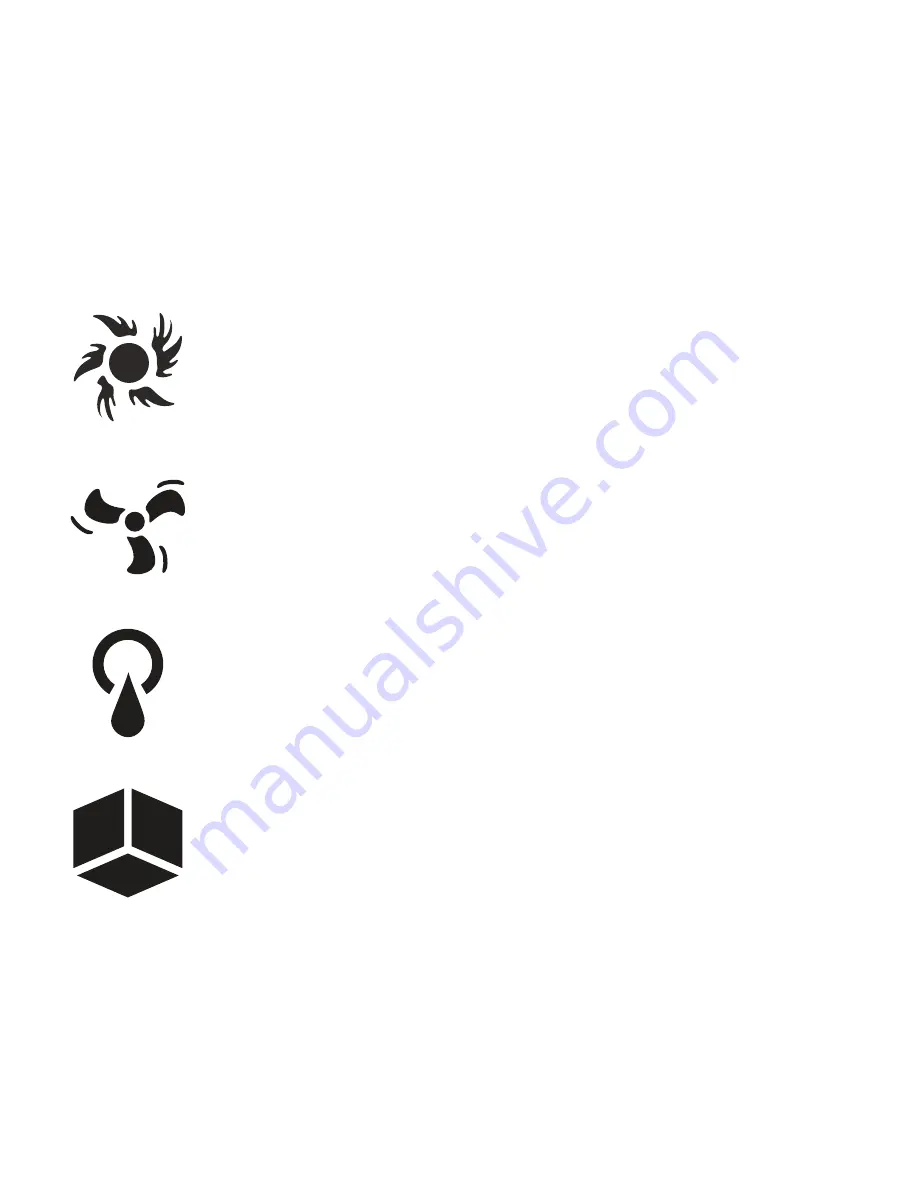
Power outlet dedicated to the lighting 

devices.

Power outlet dedicated to fan or 

extraction systems.  

Power outlet dedicated to the irrigation 

and water tank deposit maintenance 

systems.


Outlet dedicated to any other type of 

peripherals. 

If  you  connect  multiple  devices  to  one  outlet, 

remember 

not to surpass the power limits

which is for each outlet and in total per module:


2300W (230

v

AC

 - EU) / 1200W (120

v

AC

 - USA)

Summary of Contents for GroLab PowerBot

Page 1: ...INSTALLATION MANUAL www opengrow pt PowerBot ...

Page 2: ...1 4 5 10 ...

Page 3: ...6 7 12 11 ...

Page 4: ...2 3 8 9 13 ...

Page 5: ...14 16 15 ...

Page 6: ...n Manual activation push buttons Environmental sensor connection outlet Type B USB outlet Firmware updates Fuse threaded port General module switch Status signal display Universal socket outlet Perforations for vertical mounting RF communications antenna 1 2 3 4 5 6 7 8 9 10 11 12 13 ...

Page 7: ...a 13 into the module port 3 For correct communication turn the antenna in order to position it vertically according to the direction of the module Peripherals connection 1 B Type USB Only Firmware update Temperature Moisture sensor 230VAC 10A Power cord ...

Page 8: ...m flood prone areas It is recommended that the module be mounted on a wall with the fixing holes on the upper part Once the module has been mounted connect the power cable 16 to the module s power outlet 1 and the other end to the 230VAC outlet ...

Page 9: ... module s outlet 6 Place the sensor at the height of the plants where you could monitor the environmental state of the cultivation area correctly Never positon the sensor too close to a light source or to moist soil as to generate false environmental data ...

Page 10: ...e for each outlet Power outlet dedicated to the lighting devices Power outlet dedicated to fan or extraction systems Power outlet dedicated to the irrigation and water tank deposit maintenance systems Outlet dedicated to any other type of peripherals If you connect multiple devices to one outlet remember not to surpass the power limits which is for each outlet and in total per module 2300W 230vAC ...

Page 11: ...r push buttons 5 which will enable activating and deactivating manually each of the outlets The figures 10 will light up independently acting as controls and indicating at each moment which outlets are currently active ...

Page 12: ...dle the fuse holder while the module is connected to the power Turn the cover cap of the fuse holder counter clockwise with the help of a turnscrew and remove the damaged fuse Replace the fuse with another with similar features 10A 250VAC 125VDC 3AB Europe 10A 125VAC USA 2 ...

Page 13: ...nual Once GroNode has been connected to the software access GroLab through the menu If the module has been successfully located automatically by GroNode it will appear on the top menu If you have more modules of the same type a list of them will appear on the software s right side menu Add up to a total of four modules of each type for each GroNode 3 ...

Page 14: ...ding on space conditions If the control software does not find your module or frequently loses communication it is possible that you have exceeded the distance between your modules and GroNode Some load bearing walls and electronic devices may interfere with the signal Check the configuration panel to ensure the modules are connected A wireless signal icon will indicate if your module has a signal ...

Page 15: ...m persists perform a test run by placing the module next to GroNode and check the status of communication in the software If communication has been successfully re establi shed repeat this operation at different distances until you detect the maximum communication distance If GroNode does not detect your module even when next to each other contact our technical support www opengrow pt support openg...

Page 16: ...ng your devices Firmware All updates will provide crucial improvements ensuring your system s performance Connect the type B USB cable 14 to your device s USB outlet 7 and follow the procedures indicated in the firmware update manual availa ble through direct access to Guides on your desktop 4 ...

Page 17: ...ENTRIES ...

Page 18: ......

Page 19: ...disponibles à partir de l USB en anglais espagnol français allemand polonais et russe Installationsanleitungen zur Verfügung vom USB in Englisch Spanisch Französisch Deutsch Polnisch und Russisch Instrukcje dostępne z USB w języku angielskim hiszpańskim francuskim niemieckim polskim i rosyjskim instalacji Инструкции по установке доступные с USB на английском испанском французском немецком польском...

Page 20: ...ion or request more information from the technical services A guarantee claim is non transferable and only the original purchaser can submit one To enforce the guarantee the customer must always provide the purchase invoice GUARANTEE DISCLAIMER Application of the guarantee is excluded should the breakdown of the defective part or parts be a result of the product s inadequate and or negligent use U...

Reviews: