E N G I N E M E C H A N I C A L A N D M O U N T S
2 7
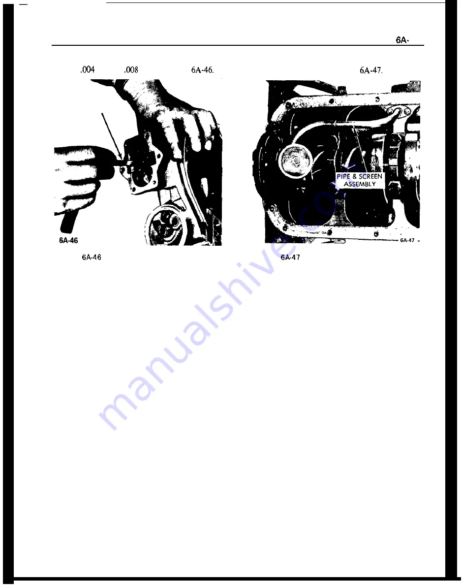
With feeler gauge, check gear backlash. It should be
between
in. and
in. See Figure
3. Remove (2) bolts holding pipe and screen assem-
bly to cylinder block. See Figure
FEELER
GAUGE
Figure
Measuring Oil Pump Gear Backlash
Checking Oil Pump Relief Valve
For Proper Functioning
1. Unscrew plug and check spring and relief valve
plunger in oil pump cover for dirt particles and free
operation. If required, carefully clean plunger and
seat. Pressure relief plunger sticking as a result of
foreign material or sludge build-up in the oil pump
cover can cause loss of oil pressure.
Removal and Inspection of Oil Pump
Pipe and Screen Assembly
1. Remove oil pan.
2. Clean oil pan. Make sure the gasket surfaces and
pan and block are clean.
Figure
Installation of Pipe and Screen
Assembly
4. Clean the screen and housing thoroughly in sol-
vent and blow dry with air stream.
Installation of Oil Pump and Screen Assembly
Install by reversing removal procedures, paying par-
ticular attention to the following points.
1. Make sure oil pump pipe flange gasket surface of
block is smooth and free of dirt.
2. Use a new gasket and install assembly.
3. Tighten pan bolts evenly. Do not over-tighten.
Torque to 5 lb. ft.
SPECIFICATIONS
BOLT TORQUE SPECIFICATIONS
Use a reliable torque wrench to tighten all parts listed, to insure proper
tightness without straining or distorting parts. These specifications are for
clean and lightly-lubricated threads only; dry or dirty threads produce in-
creased friction which prevents accurate measurement of tightness.
cardiagn.com


