background image

19

Barriers

Barrier

there is


barrier

New Barr

Barrier

beside

show barriers on the chart

Set Up Map

Show Barrier Name

barrier

barrier

New WPT

Insert to Barri

View Barr


Enter the "

" column, 

two ways to establish the 

 point.

 1) Press the MENU

key to select "

", press

ENT

key to enter the 

New 

 window, move the cursor to the "symbol" option 

 the  "Name" 

column, pressing

ENT

key appears 99 kinds of symbols (see Figure 28), press the

Arrow

keys to move the blue box onto the symbol selected, and press ENT

key, move the cursor to the "Location", input the latitude and longitude, move the 

cursor to "OK", press

ENT

key. If need to 

, press the

MODE

key to enter the charts, pressing the

MENU

key appears the menu wi-

ndow, move the cursor to "

" column, pressing the

ENT

key appears 

the map setting window, move the cursor to "

" column, press

ENT

key , and then press the ESC

key. 

2) To establish 

 points on the chart: press the Arrow

keys to move the 

cursor to the position of establishing the 

, pressing

ENT

key  appears the 

"

" window, pressing the MENU

key appears the menu window, 

move the cursor to "

" column (see Figure 29), pressing the

ENT

key appears "

" window, move the cursor to the "symbols" of the "Name" 

column, pressing

ENT

key appears 99 kinds of symbols, and then press the

Arrow

keys to move the blue box onto the symbol selected, and press ENT

key, move the cursor to the "OK"  and  press

ENT

key. 

Enter the "

" column, 

 two ways to delete 

 points. 

1) pressing the MENU

key appears the menu window, press the Arrow

keys to 

move the cursor to the "Delete" column or "Delete all" column, and then press the 

ENT

key. 

2) To remove the 

 points on the charts: move the cursor to the 

 point 

required to be  removed on the chart, pressing

ENT

key appears the "

window, move the cursor to the "Delete" and press

ENT

key.

Barrier

there are

barrier

barrier

barrier

View Barr

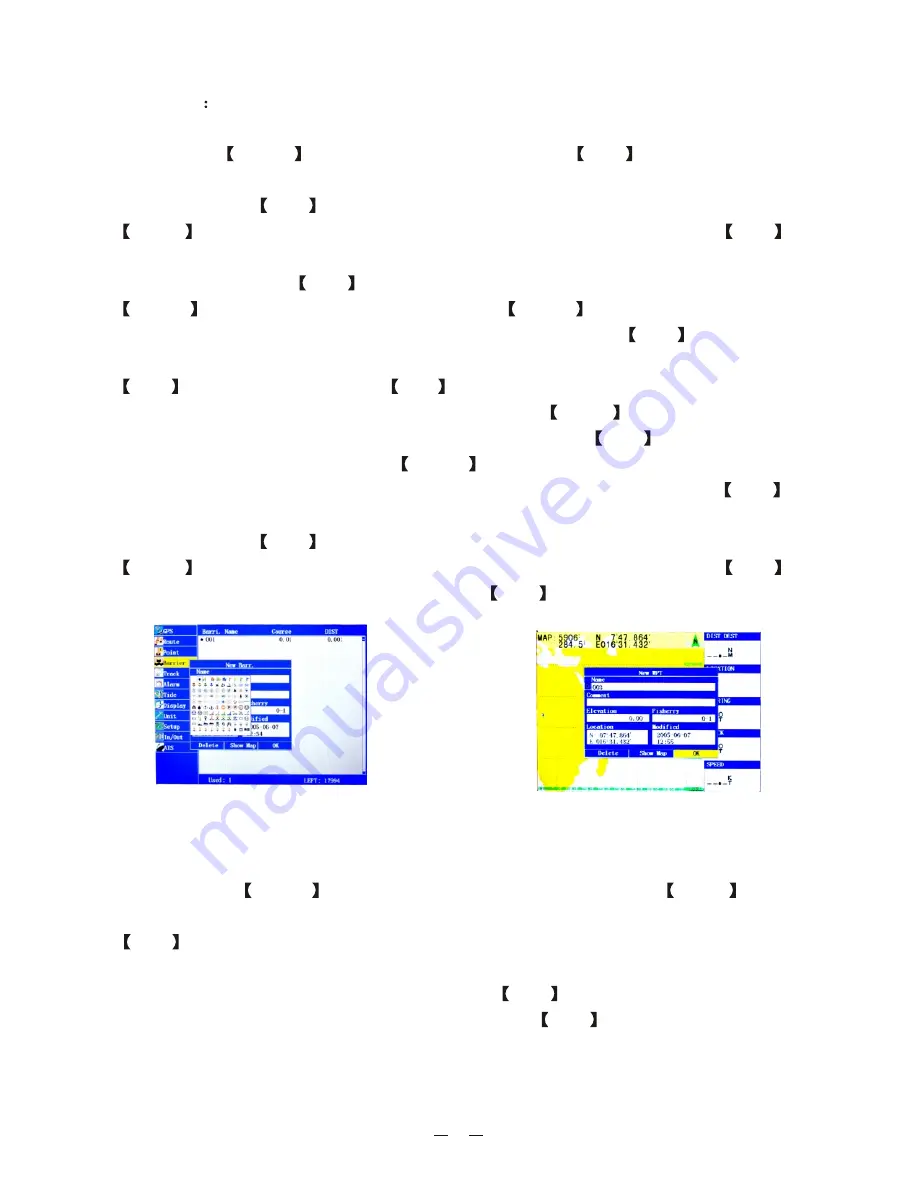
Figure 28

Figure 29

Summary of Contents for KP-622

Page 1: ...R KP 622 623 823 KP 622 623 823 OPERATOR S MANUAL 3 Series GPS Chart Plotter...

Page 2: ......

Page 3: ...1 Product Introduction...

Page 4: ...9 Turning the power on off adjusting the brightness and contrast 9 Waypoint establishment and ship s position storage 9 Delete waypoints 10 Single point navigation and cancel navigation 11 Route sett...

Page 5: ...mance and characteristics 28 Equipment parameters 28 Equipment configuration 29 Installation 30 3 Vessels list 22 The collision alarm 22 Own ships info rmation 23 Chart Screen 23 View AIS vessels info...

Page 6: ...sonable can be easy to use The built in Large capacity map storage space provides intuitive and accurate indication to navigation It s applicable to the navigation and position fixing of various vesse...

Page 7: ...verse cycle order ENT Confirms the input or data Arrow Move the cursor or select the number or letter MODE Display the four main screens circularly turn over the listed interfaces MOB The MOB mark den...

Page 8: ...see Figure 2 Route screen AIS Radar View and Position screen see Figure 3 Keep pressing arrow key displays accordingly the four main screens by a posit ive cycle keep pressing exit key displays them...

Page 9: ...he navigation of the vessel is beyond the plotter screen the vessel will be automatically centered Hide Data Window Hide the data field enlarge the plotter screen Set Data Fields Change the items show...

Page 10: ...eys to move the cursor to the north up column then press ENT key the top of the compass should be the direction of the north Press the left right Arrow keys to rotate the direction of the compass See...

Page 11: ...rrow keys to move the cursor to the position which required to establish the waypoints and press ENT key then press ENT key again this equipment will automatically estab lish and number the new waypoi...

Page 12: ...onfirm Delete All 10 Then move the cursor to OK column and press the ENT key to complete the establishment of a new waypoint See Figure 13 Position storage and the estab lishment of a new waypoint Aft...

Page 13: ...int 2 2 5 Route setting and route navigation New routes 1 Press the MENU key twice to enter the main menu move the cursor to the Route column and press the MENU key to enter the sub menu move the curs...

Page 14: ...key to enter the screen and set the route name then press the ENT key move the cursor to the next column and press the ENT key displays the list of the waypoints move the cursor to the waypoint and p...

Page 15: ...methods may regulate the interval pause etc at any time during the process of recording A total of 40 track lines 2100 track points for each track can store 84 000 track points in total New track Sto...

Page 16: ...e start a new track record The Wrap mode is When it reaches the 2100 track points for the current record remove the track point on the end of track line and store the newest track point make a cycle u...

Page 17: ...unit for track record interval and records 1 track point in a specified distance range The smallest distance interval is 0 01 nm about 18 m Choosing a suitable interval value for the track record can...

Page 18: ...ss the right Arrow key to move the cursor to the track need to be edited press MENU key see Figure 23 Open Display Close Display Open Display Close Display it is Move the cursor to Copy or Delete or D...

Page 19: ...nes set to be Track dis play on will be displayed on the chart screen The ALL means under any scale the track lines set to be Track display on will all be displayed on the chart screen To set track li...

Page 20: ...e satellite signal strength The latitude and longit ude whose color turns into black color is the positioning latitude and longitude See Figure 26 Route Enter the Route column and press the MENU key m...

Page 21: ...T key and then press the ESC key 2 To establish points on the chart press the Arrow keys to move the cursor to the position of establishing the pressing ENT key appears the window pressing the MENU ke...

Page 22: ...key the tides situation of the major ports along the coast on any parti cular date can be found Move the cursor to the Tide screen press the left right Arrow keys the time of the high low tides on th...

Page 23: ...well as the habits Time Zone Enter the local time zone Users may set up the charts display setting according to the needs that is upper for the north upper for the East upper for the South or upper fo...

Page 24: ...S vessels received by the current AIS equipment See Figure 35 Data In Out Device 4 3 The collision alarm Enter the Main Menu and select the Alarm and then select the scope of the collision alarm accor...

Page 25: ...ship s information Enter the vessels list and press the MENU key and then select the to check all the information of own ship see Figure 37 The own ship s information is also displayed on the upper r...

Page 26: ...of the triangle stands for the current direction of the own ship the blue hollow triangle stands for the vessels of CLASS B the green hollow tria ngle stands for CLASS A vessels the green hollow squar...

Page 27: ...There are two ways for Entry Departure setting 1 Press the MENU key at the Radar window and select or See figure 43 2 Press the NAV key at any window and select or See figure 44 In Port Out Port In Po...

Page 28: ...estination The estimated time you will reach a Goto destination or the final waypoint in a route ETA at Next The estimated time you will reach a Goto destination or the next waypoint in a route Cross...

Page 29: ...tioning data once per second 5 1 2 Navigation 1 Up to 18 000 waypoints including the optional logo or as geographic information 2 Up to 50 routes 50 300 waypoints for each route 3 Track Points 40 Trac...

Page 30: ...display KP 622 5 7 119mm 97mm 320 240 dot matrix 8 grades of gray liquid crys tal display KP 623 5 7 119mm 97mm 640 480 dot matrix TFT color LCD display 5 Temperature 30 to 65 working temperature 35 t...

Page 31: ...29 5 1 6 Installation see Figure 45 Figure 45 a Desktop installation Figure 45 b installation Panel Figure 45 c Ceiling installation...

Page 32: ...8 RS 232 RXD PIN 5 RTCM RXD or other PIN 3 USB PIN 4 USB PIN 2 Sound output 8 1W Power 10 38V DC RXD TXD AIS NMEA 0183 Equipment DGPS RTCM USB USB USB PC Red Black Yellow Orange Brown Blue Green Wirle...

Page 33: ......

Reviews: