background image


28


Connecting Your  Components


—Continued


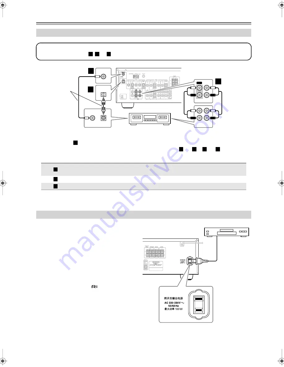
• With the basic 

 connection, you can play and record with the recorder.

• To connect the recorder digitally for playback purposes, use connections 

 and 

 or 

 and 

The AV receiver has an AC outlet on its rear panel for 
connecting the power cord of another AV component. 
The other component’s power switch can then be left in 
the ON position so that it turns on or off when the AV 
receiver is set to On or Standby.


Caution:


• Make sure that the capacity of the component that 

you connect to the AC OUTLET does not exceed 
the stated capacity (e.g., 100 W).


Notes:


• Onkyo components with 

 jacks should be con-

nected directly to wall outlets, not the AV 
receiver’s AC OUTLET.

• The socket type and capacity will depend on the 

country in which you purchased the AV receiver.


Connecting a Cassette, CDR, MiniDisc, or DAT Recorder


Connection

TX-SR403/8340

Signal flow

Cassette/CDR/MD/DAT recorder


TAPE IN L/R

TAPE OUT L/R


Analog audio L/R output

Analog audio L/R input

DIGITAL IN COAXIAL


Digital coaxial output

DIGITAL IN OPTICAL


Digital optical output


Connecting the Power Cord of Another Component

OUT

REC PLAY

IN OUT

L

R

L

R

IN

TAPE

L

R

OPTICAL

OPTICAL

OUT

DIGITAL IN

COAXIAL

COAXIAL

OUT

Step 1:

Choose a connection type (

, or 

) that matches the recorder, and then make the connection.

a

b

c

a

b

c

Cassette recorder, CDR, 
etc.

Connect one

or the other

a

a

b

a

c

a

b

c

TX-SR403̲En.book Page 28 Friday, April 29, 2005 10:55 AM

Summary of Contents for TX-SR403

Page 1: ...structions in this manual will enable you to obtain optimum performance and listening enjoyment from your new AV Receiver Please retain this manual for future reference Contents Introduction 2 Connection 15 Turning On First Time Setup 30 Basic Operation Playing your AV components 34 Using the Tuner 36 Enjoying the Listening Modes 40 Advanced Operation 44 Troubleshooting 50 Specification 53 ...

Page 2: ...paratus does not operate normally by following the operating instructions Adjust only those controls that are covered by the operating instructions as an improper adjustment of other controls may result in damage and will often require extensive work by a qualified technician to restore the apparatus to its normal operation E If the apparatus has been dropped or damaged in any way and F When the a...

Page 3: ...ect voltage for your area Setting the STANDBY ON switch to STANDBY does not fully shutdown the unit If you do not intend to use the unit for an extended period remove the power cord from the AC outlet 5 Never Touch this Unit with Wet Hands Never handle this unit or its power cord while your hands are wet or damp If water or any other liquid gets inside this unit have it checked by your Onkyo deale...

Page 4: ...untry Speaker cable labels Front Left Front Left SP B Zone 2 Left SP B Zone 2 Left Surround Right Surround Right Surround Back Right Surround Back Right Zone 2 Right Zone 2 Right Front Left Front Left SP B Zone 2 Left SP B Zone 2 Left Front Right Front Right SP B Zone 2 Right SP B Zone 2 Right Front Right Front Right SP B Zone 2 Right SP B Zone 2 Right Surround Right Surround Right Center Center C...

Page 5: ...Remote Controller Remote controller can be used to control Onkyo CD CDR MD components and cassette tape deck Table of Contents Important Safety Instructions 2 Precautions 3 Supplied Accessories 4 Features 5 Front Rear Panels 6 Before Using the AV receiver 9 Remote Controller 10 Connecting Your Speakers 15 Connecting Antenna 18 Connecting Your Components 20 Turning On 30 First Time Setup 31 Playing...

Page 6: ...AM or FM input source is selected the TUNING buttons are used to tune the tuner and the PRESET buttons are used to select radio presets see page 37 When the setup menus are used they work as arrow buttons and are used to select and set items The ENTER button is also used with the setup menus M MASTER VOLUME control 34 This control is used to adjust the volume of the AV receiver to MIN 1 through 79...

Page 7: ...nd digital audio format 4 Tuning indicators 36 TUNED 36 This indicator lights up when the AV receiver is tuned to a radio station AUTO 36 This indicator lights up when Auto Tuning is selected and disappears when Manual Tuning is selected MEMORY 37 This indicator lights up when pre setting radio stations FM STEREO 36 This indicator lights up when the AV receiver is tuned to a stereo FM station 5 SL...

Page 8: ...IN OUT jacks can be used to connect a VCR The VIDEO 2 IN jack can be used to connect another video source e g cable TV satellite TV or a set top box I CD IN These analog inputs can be used to connect a CD player with analog outputs J TAPE IN OUT These analog inputs and outputs can be used to con nect a cassette recorder MiniDisc recorder or other recorder with analog inputs and outputs K S VIDEO M...

Page 9: ... mind when installing If another remote controller of the same type is used in the same room or the AV receiver is installed close to equipment that uses infrared rays the remote control ler may not work reliably Don t put anything such as a book on the remote con troller because the buttons may be pressed inadvert ently thereby draining the batteries The remote controller may not work reliably if...

Page 10: ...ts RECEIVER mode is used to control the AV receiver To set the remote controller to RECEIVER mode press the RECEIVER REMOTE MODE button How to Use the Remote Controller 1 Use the REMOTE MODE buttons to select a mode 2 Use the buttons supported by that mode to control the component RECEIVER mode see page 10 DVD mode see page 12 CD MD CDR mode see page 13 TAPE mode see page 14 TAPE AMP RECEIVER CDR ...

Page 11: ...REO button This button selects the Stereo listening mode SURROUND button This button selects the Dolby and DTS listening modes buttons These buttons can be used to select any of the avail able listening modes K TEST TONE CH SEL LEVEL LEVEL buttons 33 These buttons are used to adjust the level of each speaker L DISPLAY button 35 This button is used to display various information about the currently...

Page 12: ...used to display information about the current disc title chapter or track on the DVD player s display including the elapsed time remain ing time total time and so on L CLR button This button is used to cancel functions and to clear entered numbers M MENU button This button is used to display a DVD s menu N SETUP button This button is used to access the DVD player s onscreen setup menus O RANDOM bu...

Page 13: ...e total time and so on G CLR button This button is used to cancel functions and to clear entered numbers H RANDOM button This button is used with the random playback func tion I REPEAT button This button is used to set the repeat playback func tions J PLAY MODE button This button is used to select play modes on a com ponent with selectable play modes CD MD CDR Mode Before selecting a mode and star...

Page 14: ... The Rewind button is used to start rewind The FF button is used to start fast forward TAPE Mode Before selecting TAPE mode and starting play back you should press the RECEIVER REMOTE MODE button followed by the TAPE INPUT SELECTOR button to select your cas sette recorder as the input source MUTING MENU TOP MENU SP A B SETUP RETURN RANDOM SUBTITLE PLAY MODE AUDIO REPEAT RC 605S TAPE AMP ON STANDBY...

Page 15: ... speaker enhances the front left and right speakers making sound movements distinct and providing a full sound image In movies it s used mainly for dialog Position it close to your TV preferably on top facing forward at about ear level or at the same height as the front left and right speakers Subwoofer The subwoofer handles the bass sounds of the LFE Low Frequency Effects channel The volume and q...

Page 16: ...e corresponding speaker terminal Read the following before connecting your speakers You can connect speakers with an impedance of 6 ohms or higher If you use speakers with a lower impedance and use the amplifier at high volume lev els for a long period of time the built in protection circuit may be activated Disconnect the power cord from the wall outlet before making any connections Read the inst...

Page 17: ...illustration shows which speaker should be connected to each pair of terminals Connecting Speaker 1 Strip 3 8 10 mm of insu lation from the ends of the speaker cables and twist the bare wires tightly as shown 2 While pressing the lever insert the wire into the hole and then release the lever Make sure that the terminals are gripping the bare wires not the insulation 3 8 10 mm Connecting a Powered ...

Page 18: ...o tune into an FM radio station and adjust the position of the FM antenna to achieve the best possible reception 2 Fully extend the antenna and point it in various directions to find the best recep tion Secure it in that position with thumb tacks or something similar AM antenna push terminals FM antenna jack Insert the plug fully into the jack Insert the plug fully into the jack Connecting the AM ...

Page 19: ...th local regulations to prevent electrical shock haz ards Using a TV FM Antenna Splitter It s best not to use the same antenna for both FM and TV reception as this can cause interference problems If cir cumstances demand it use a TV FM antenna splitter as shown If good reception cannot be achieved using the supplied AM loop antenna an outdoorAM antenna can be used in addition to the loop antenna a...

Page 20: ...les AV Cables Jacks About AV Connections Left white Right red Yellow Analog audio Composite video Left white Right red Yellow Right Wrong Video Cable Jack Description S Video cable S Video separates the luminance and color signals and provides better picture quality than composite video Composite video cable Composite video is commonly used on TVs VCRs and other video equipment Use only dedicated ...

Page 21: ...ayer to the S VIDEO DVD IN a video signal will be output by the S VIDEO MONITOR OUT for your TV and the S VIDEO VIDEO 1 OUT for your VCR but not by any composite video output Video Input Output Diagram Audio Connection Formats Audio equipment can be connected to the AV receiver using the following audio connection formats analog optical coaxial and multichannel When choosing a connection format be...

Page 22: ...omposite video input Standard Connection TX SR403 8340 Signal flow TV VIDEO 2 IN L R Analog audio L R output DIGITAL IN COAXIAL Digital coaxial output DIGITAL IN OPTICAL Digital optical output S VIDEO IN VIDEO IN MONITOR OUT VIDEO S VIDEO MONITOR OUT Step 1 Video Connection Choose a connection type or that matches the TV and then make the connection A B TV projector etc A B A B OPTICAL OPTICAL OUT...

Page 23: ...IDEO OUT IN DVD VIDEO OUT IN S VIDEO DVD VIDEO Step 1 Video Connection Choose a connection type or that matches the DVD player and then make the connection A B DVD player A B The TV must be connected to the AV receiver with the same type of connection A B Connection TX SR403 8340 Signal flow DVD player DVD IN FRONT Analog audio L R output DIGITAL IN COAXIAL Digital coaxial output DIGITAL IN OPTICA...

Page 24: ...etter VIDEO VIDEO 1 IN Composite video output Standard S VIDEO OUT VIDEO OUT VIDEO 1 IN IN VIDEO S VIDEO VIDEO 1 Step 1 Video Connection Choose a connection type or that matches the VCR DVD recorder and then make the connection The TV must be connected to the AV receiver with the same type of connection A B A B VCR DVD recorder A B Connection TX SR403 8340 Signal flow VCR DVD recorder VIDEO 1 IN L...

Page 25: ...r console VIDEO 3 IN Composite video output VIDEO 3 IN L R Analog audio L R output L R L R VIDEO 1 AUDIO IN S VIDEO IN VIDEO IN VIDEO 1 VIDEO S VIDEO VIDEO 1 Step 1 Choose a video connection type or that matches the VCR DVD recorder and make the connection The video source that you want to record must be connected to the AV receiver with the same type of connection Step 2 Make audio connection A B...

Page 26: ... Step 1 Video Connection Choose a connection type or that matches the video source and then make the connection A B A B Satellite cable set top box etc The TV must be connected to the AV receiver with the same type of connection A B Connection TX SR403 8340 Signal flow Video source VIDEO 2 IN L R Analog audio L R output DIGITAL IN COAXIAL Digital coaxial output DIGITAL IN OPTICAL Digital optical o...

Page 27: ... Player or Turntable Connection TX SR403 8340 Signal flow CD or turntable CD IN L R Analog audio L R output DIGITAL IN COAXIAL Digital coaxial output DIGITAL IN OPTICAL Digital optical output IN L R L R CD AUDIO OUTPUT OPTICAL OPTICAL OUT AUDIO OUT L R DIGITAL IN COAXIAL COAXIAL OUT L R IN CD Step 1 Choose a connection type or that matches the CD player or choose for a turntable with a built in ph...

Page 28: ...Onkyo components with jacks should be con nected directly to wall outlets not the AV receiver s AC OUTLET The socket type and capacity will depend on the country in which you purchased the AV receiver Connecting a Cassette CDR MiniDisc or DAT Recorder Connection TX SR403 8340 Signal flow Cassette CDR MD DAT recorder TAPE IN L R TAPE OUT L R Analog audio L R output Analog audio L R input DIGITAL IN...

Page 29: ...cks Notes Use only cables for connections cables are supplied with Onkyo players DVD CD etc Some components have two jacks you can connect either one to the AV receiver The other is for connecting additional compatible compo nents Connect the AV receiver s jack to only Onkyo components Connecting to other manufacturer s components may cause them to malfunction Some components may not support all f...

Page 30: ...he AV receiver off press the STANDBY ON button or the remote control ler s STANDBY button The AV receiver will enter Standby mode To prevent any loud surprises the next time you turn on the AV receiver always turn down the volume before turning it off STANDBY ON Remote controller AV receiver or RECEIVER Smooth Operation in a Few Easy Steps To ensure smooth operation here s a few easy steps to help...

Page 31: ...ce that you want to assign Digital inputs cannot be assigned to the TUNER input source 2 Press the DIGITAL INPUT button The current assignment appears 3 Press the DIGITAL INPUT but ton repeatedly to select COAX OPT or analog TONE STEREO LISTENING MODE DISPLAY DIGITAL INPUT DIMMER MEMORY TUNING MODE RETURN TUNING PRESET ENTER SETUP STANDBY STANDBY ON CLEAR PHONES MULTl CH DVD VIDEO 1 VCR VIDEO 2 VI...

Page 32: ...VER 2 Use the Up and Down buttons to select 1 Speaker Config and then press the ENTER button 3 While the Subwoofer setting is selected use the Left and Right buttons to select Yes or No Yes Select if a subwoofer is con nected No Select if no subwoofer is con nected 4 Use the Down button to select Front and then use the Left and Right buttons to select Small or Large Small Select if the front speak...

Page 33: ... the Surround setting in step 6 is set to None this setting does not appear If the Surround setting in step 6 is set to Small the Large option cannot be selected 8 Press the SETUP button Setup closes TESTING THE SPEAKERS To test that all of the speakers are working properly press the remote controller s TEST TONE but ton The test tone will be output by each speaker in turn and the name of each spe...

Page 34: ...er or the SP A B button on the remote controller to select the speaker set that you want to use Pressing the remote controller s SPA B button cycles through the following settings Speaker Set A Speaker Set A B Speaker Set B Off The A and B speaker indicators show whether each speaker set is on or off Note that when speaker set B is turned on speaker set A is reduced to 2 1 channel playback 3 Start...

Page 35: ... dis played information reappears Interpreting Surround Channel Information A The number of front channels front left front right and center B The number of surround channels surround left and surround right If there s surround back channel information this number will be 3 C LFE channel for subwoofer 1 means yes Using the Multichannel Input Press the RECEIVER button fol lowed by the MULTI CH butt...

Page 36: ...mple FM has been selected Actual display depends on country 1 Press the SETUP button and use the Up and Down buttons to select 0 Hardware Setup and then press ENTER 2 Use the Up and Down buttons to select AM Freq and then use the Left and Right buttons to select 10 kHz Select if 10 kHz steps are used in your area 9 kHz Select if 9 kHz steps are used in your area 3 Press the SETUP button Setup clos...

Page 37: ... TUNER CD MASTER VOLUME A SPEAKERS B 2 4 3 MEMORY TUNING PRESET ENTER MEMORY TONE STEREO LISTENING MODE DISPLAY DIGITAL INPUT DIMMER MEMORY TUNING MODE RETURN TUNING PRESET ENTER SETUP STANDBY STANDBY ON CLEAR PHONES MULTl CH DVD VIDEO 1 VCR VIDEO 2 VIDEO 3 TAPE TUNER CD MASTER VOLUME A SPEAKERS B 1 TUNING PRESET ENTER 1 Select the preset that you want to delete See the previous section 2 While ho...

Page 38: ...ng the Display Brightness Press the DIMMER button repeatedly to select dim dim mer or normal brightness MUTING MENU TOP MENU SP A B SETUP RETURN RANDOM SUBTITLE PLAY MODE AUDIO REPEAT RC 605S TAPE AMP ON STANDBY DIMMER SLEEP INPUT SELECTOR REMOTE MODE V1 V2 V3 CD TAPE TUNER DVD MULTI CH LISTENING MODE DISPLAY TESTTONE CH SEL SURROUND STEREO CINE FLTR LEVEL LEVEL L NIGHT VOL CDR MD DVD RECEIVER CD ...

Page 39: ...s on you can also adjust the levels of the left and right speakers in speaker set B from 12 dB to 12 dB These settings are stored when the AV receiver is set to Standby While speaker set B is on you can adjust the levels of the left and rigt speakers in speaker setA s and the sub woofer Headphones While a pair of headphones is connected you can adjust the volume of the left and right channels indi...

Page 40: ...ur rent input source Selecting Listening Modes The Dolby Digital and DTS listening modes can only be selected if your DVD player is connected to the AV receiver with a digital audio connection coaxial or optical Listening mode availability depends on the format of the current input signal While a pair of headphones is connected or speaker B is on you can select only the Mono Direct or Stereo liste...

Page 41: ...S Multich 2 2 0 Stereo 1 0 1 1 Other 3 2 1 2 0 Stereo DTS ES Discrete Matrix Source Listening mode CD TV VHS MD turntable radio cassette DTV etc DVD DTV etc DVD CD etc DVD Direct Stereo Mono Multich PLIIx Movie Music Game 3 Neo 6 Cinema Neo 6 Music 4 3 If the Surr Back parameter is set to None PLII is used 4 Available only when Surround speakers are connected Dolby Dolby D Dolby D EX Dolby D PLIIx...

Page 42: ...hree modes of operation Movie mode for movies Music mode for listening to music and Game mode for use with games consoles with 2 channel stereo outputs Dolby Digital With this format you can experience the same superb sound that you get at a movie theater or concert hall Use this mode with DVDs that bear the Dolby Digital logo Dolby Digital EX With an added surround back channel this 6 1 channel f...

Page 43: ...usic CDs Onkyo Original DSP Modes Mono Movie This mode is suitable for use with old movies and other mono sound sources The center speaker outputs the sound as it is while reverb is applied to the sound output by the other speakers giving presence to even mono material Orchestra Suitable for classical or operatic music The surround channels are emphasized in order to widen the stereo image In addi...

Page 44: ...ons only work with speaker set A Audio Adjust provides various functions for adjusting the sound Using the Late Night Function Dolby Digital only 1 Press the RECEIVER button and then press the L NIGHT but ton repeatedly to select Off Late Night function off Low Small reduction in dynamic range High Big reduction in dynamic range MUTING MENU TOP MENU SP A B SETUP RETURN RANDOM SUBTITLE PLAY MODE AU...

Page 45: ...Logic II Music or Pro Logic IIx Music listening mode Normally if you re using a center speaker the center channel sound is output by only the center speaker If you re not using a center speaker the center channel sound will be distrib uted to the front left and right speakers to create a phan tom center This setting controls the front left right and center mix allowing you to adjust the weight of ...

Page 46: ...rce you can watch the video from theVIDEO 3 input and listen to the audio from the CD input In the following example audio from the CD player con nected to the CD IN jacks and video from the camcorder connected to the VIDEO 3 IN jack are recorded by the VCR which is connected to the VIDEO 1 OUT jacks 1 Prepare the camcorder and CD player for playback 2 Prepare the VCR for recording 3 Press the VID...

Page 47: ...ontroller 2 Use the Up and Down buttons to select 1 Speaker Config and then press the ENTER button 3 Use the Down button to select Crossover and then use the Left and Right but tons to select a crossover fre quency Choose a crossover frequency suitable for your setup If you re using a subwoofer choose a crossover frequency based on the diam eter of your front speakers If you re not using a subwoof...

Page 48: ...ress the RECEIVER button fol lowed by the SETUP button on the remote controller 3 Use the Up and Down buttons to select 2 Sp Dis tance and then press the ENTER button 4 While Unit is displayed use the Left and Right buttons to select feet or meters feet Distances in feet Can be set from 1 to 30 feet in 1 foot steps meters Distances in meters Can be set from 0 3 to 9 meters in 0 3 meter steps 5 Use...

Page 49: ... and use the Down but ton to select the next speaker The level can be adjusted from 12 to 12 dB in 1 dB steps 15 to 12 dB for the subwoofer 5 Repeat step 4 so that the level of the test tone from each speaker is the same Speakers that you set to No or None in the Speaker Configuration page 32 do not output the test tone 6 Press the SETUP button Setup closes Don t forget to turn down the volume if ...

Page 50: ...o discs you need to select an audio format from a menu If your turntable doesn t have a phono preamp built in you must connect one between it and the AV receiver If your turntable uses an MC cartridge you must con nect an MC head amp or an MC transformer and a phono preamp Specify the speaker distances and adjust the individual speaker levels pages 48 49 The input signal format is set to PCM or DT...

Page 51: ... to PCM because the AV receiver does not switch formats immediately you may not hear any sound in which case you should stop your player for about three seconds and then resume play back With some CD players you won t be able to playback DTS material properly even though your player is con nected to a digital input on the AV receiver This is usually because the DTS bitstream has been processed e g...

Page 52: ...mode is set to Stereo unless it s already set to Stereo Mono or Direct How do I change the language of a multiplex source Use the Multiplex setting on the 4 Audio Adjust menu to select Main or Sub page 45 The functions don t work To use you must make an connection and an analog audio connection RCA between the compo nent and AV receiver even if they are connected digi tally page 29 Remote Controll...

Page 53: ... Y 0 28 Vp p 75Ω S Video C 1 Vp p 75Ω Composite Tuning Frequency Range 87 5 MHz 108 0 MHz Usable Sensitivity Stereo 17 2 dBf 2 µV 75Ω IHF Mono 11 2 dBf 1 µV 75Ω IHF Signal to Noise Ratio Stereo 70 dB IHF A Mono 76 dB IHF A THD Stereo 0 3 1kHz Mono 0 2 1kHz Frequency Response 30 Hz 15 kHz 1 dB Stereo Separation 45 dB 1kHz Tuning Frequency Range 522 kHz 1611 kHz 530 kHz 1710 kHz Usable Sensitivity 3...

Page 54: ...54 Memo ...

Page 55: ...55 Memo ...

Page 56: ... 6 82194 Groebenzell GERMANY Tel 49 8142 4401 0 Fax 49 8142 4401 555 http www eu onkyo com ONKYO EUROPE UK Office Suite 1 Gregories Court Gregories Road Beaconsfield Buckinghamshire HP9 1HQ UNITED KINGDOM Tel 44 0 1494 681515 Fax 44 0 1494 680452 ONKYO CHINA LIMITED Units 2102 2107 Metroplaza Tower I 223 Hing Fong Road Kwai Chung N T HONG KONG Tel 852 2429 3118 Fax 852 2428 9039 http www ch onkyo ...

Reviews: