


35
6.2.
Switching Scenes on the Vision Sensor
For a processing to switch scenes on the Vision Sensor, follow the procedures below.
1
Set a scene number for the switching destination to a variable.
'(1) Change the scene of the FH
' You have to select a scene No. for your application.
fh_sceneno_input = 0
2
Set the variables as arguments to the scene switching command execution
sample function (fhsample_chgscn) to the Vision Sensor and execute it.
CallProc fhsample_chgscn(fh_sceneno_input)
'Error check
If fh_err_number <> fh_success
GoTo *CLOSE_SAMPLE
ENDIF
6.3.
Moving Robot to Robot Image Position
For a processing to move the robot to the robot image position, follow the procedures
below.
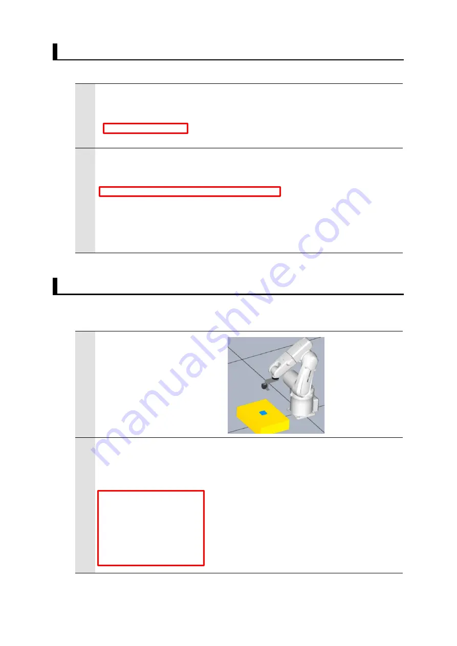
1
Move the robot to the imaging
position.
Check the current robot
position (Precautions unit of
the Rotation Vector).
2
Set the referenced imaging position to the variables.
'(2) Move the robot to the imaging position
' You have to configure the following robot position for your application.
fh_move_position[1] = 0 'std_img_pos_x
fh_move_position[2] = -240 'std_img_pos_y
fh_move_position[3] = 600 'std_img_pos_z
fh_move_position[4] = -180 'std_img_pos_w
fh_move_position[5] = 0 'std_img_pos_p
fh_move_position[6] = 90 'std_img_pos_r
Scene number
Scene switching command execution sample function
Set the robot imaging position to the variables.


