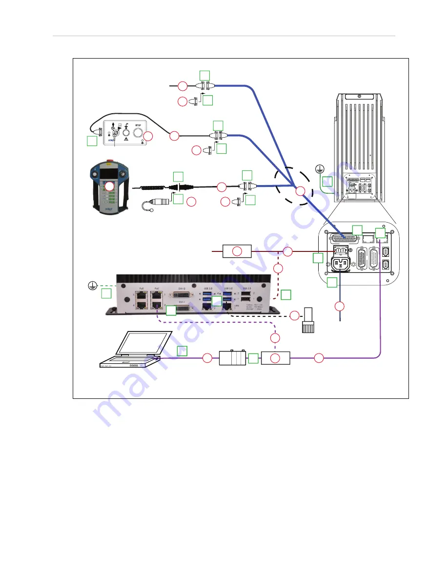
1.6 Configuration
DC
IN
24 V
GND
AC
200 -
240 V
Ø
1
XBEL
TI
O
XIO
Servo
ENET
ENET
XSYSTEM
ePLC Quattro Robot
24 VDC, 6 A
Power Supply
200-240 VAC
10 A
single-phase
AC Power
Cable
DC Power
Cable
Front Panel
Cable
Front Panel
User-Supplied PC
running PLC
Programming Software
T20 Adapter
Cable
XMCP Jumper Plug
XMCP
XFP
XUSR
XUSR Jumper Plug
eAIB
XSYSTEM
Cable
Robot Interface
Panel
XUSR for:
- User E-Stop/Safety Gate
- Muted Safety Gate
The Jumper Plug is required if
neither of these is used
Ethernet from
PC to PLC
T20 Bypass Plug
User-Supplied
Ground Wire
T20 Pendant (option)
Either T20 Pendant,T20 Bypass Plug, or
XMCP Jumper Plug must be used
2
3
4a
A
B
G
H
J
4a
4
4
1
5
6
7
9
8
L
M
Q
P
E
K
D
N
3
85 - 264 VAC
Universal
Input
DC
IN
24V
GND
AC
200 -
240V
Ø
1
XBEL
TIO
XIO
Servo
ENET
ENET
XSYSTEM
Ethernet from
PLC to eAIB
FP Jumper Plug
F
Either Front Panel or
FP plug must be used
3a
2a
C
Ethernet from eAIB
to SmartVision MX
R
9b
9a
User-supplied
Switch
SmartVision MX (option)
Camera
(option)
User-Supplied
Ground Wire
5a
7a
M
T
10
DC Power
Cable
S
PLC
Figure 1-4. Configuration with Vision
1.6 Configuration
The user-supplied PLC and the Quattro robot are connected either through a shared network or
via a user-supplied Ethernet cable.
When the Quattro ePLC robot is powered on and waiting for a PLC connection, the robot
status panel will display its IP address, two digits at a time.
The format will be:
IP xxx-xxx-xxx-xxx OK
Quattro ePLC650/800 Quick Setup Guide, 13588-000 Rev D
Page 10 of 16
Summary of Contents for Quattro 650H
Page 1: ...I598 E 01 Quick Setup Guide Quattro 650H 650HS 800H 800HS ePLC...
Page 14: ......
Page 15: ......


