background image

7

OS3101

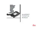
Wiring for Connection to the G9SA-301 Controller (Category 3)

M1

OUT

PLC

KM1

KM2

IN1

IN2

KM3

A1

T23

PE

14

24

34

42

41

33

23

13

T32

T31

T11

A2

KM1

KM2

KM1

KM2

S3

T12

K1

K1

K2

K1

T21

6

a

K2

K2

b

T22

A

B

a

b

2

5

1

3

4

1

2

3

4

5

6

Control
circuit

JP

Shield (protective earth)

24 VDC (white 

×

 2)

0 VDC (brown 

×

 2)

Area selection 1 (orange/white)

Area selection 2 (orange/black)

Area selection COM (black)

Start (gray)

Auxiliary output (blue)

Alarm output (red/black)

EDM (pink)

Control output B (red)

Control output A (yellow)

S1

*

1

*

2

S1: Start input (used to cancel lockout)
S2-1/S2-2:  Area setting selector
 When 

area setting 1 is selected: S2-1 is short-circuited, S2-2 is open

 When 

area setting 2 is selected: S2-1 is open, S2-2 is short-circuited

 (For 

details, refer to the Instruction Manual.)

S3: Reset switch
KM1, KM2: Safety relays with forcibly guided contacts
M1: 3-phase motor
E1: 24-VDC power supply
PLC: Programmable Controller (For monitoring use. Not related to the safety system.)

OS3101 Settings

 Disable EDM

 Auto start

+

24 V

0 V

E1

S2-2

S2-1

*1.

Use NC contacts for the start input.

*2.

If the EDM is not used, connect the wire (pink) to 1 VDC, and then use the setting software to set the EDM to OFF.

Summary of Contents for OS3101

Page 1: ...s and at robot stations th e OS3101 can be mounted onto automated guided ve hicles AGVs and other mobile objects for which the monitoring area must be frequent ly switched duri ng obstacle detection Be sure to read the Safety Precautions on page 13 D T V Light 2 Operating Principle Angular encoder Axis of rotation Detectable object Stopwatch Sampling Start Start Stop Receiver Emitter Motor Reflect...

Page 2: ... preset allowing the OS3101 to respond to even complex changes in the work environment The patterns can be switched using only the OS3101 without having to use the special Controller to quickly meet the needs of various work steps Protective area Warning area Protective area Warning area OS3101 OS3101 OS3101 OS3101 Safety Light Curtain Safety Light Curtain Automated guided vehicle AGV Automated pr...

Page 3: ...o high capacity PNP transistor control outputs allow direct connection of output equipment such as safety relays and contactors with rated current up to 625 mA at 24 VDC The OS3101 also features an external device monitor EDM that makes it possible to configure safety circuits to the Category 3 level without having to use the Controller Response Time from 80 ms to a Maximum of 680 ms The response ...

Page 4: ...39 RS2 C4 Appearance Specification Model Remarks L shaped Mounting Brackets OS3101 BKT Includes two L shaped Mounting Brackets two positioning brackets and screws to mount the Safety Laser Scanner to the L shaped Mounting Brackets Rear Surface Mounting Brackets OS3101 BPT Includes Rear Surface Mounting Brackets and screws to mount the L shaped Mounting Brackets to the Rear Surface Mounting Bracket...

Page 5: ...to start start interlock start restart interlock Inputs EDM ON Short circuit current of 0 V input current 50 mA OFF open Start ON Short circuit current of 0 V input current 20 mA OFF open Area selection ON Connected to area selection COM input current 20 mA OFF open Connection type Power cable 14 pin special round connector Communications cable RS 232C 9 pin D sub connector straight cable Connecti...

Page 6: ...k to 0 VDC and then use the setting software to set the EDM to OFF Shield protective earth 24 VDC white 2 0 VDC brown 2 Area selection 1 orange white Area selection 2 orange black Area selection COM black Start gray Auxiliary output blue Alarm output red black EDM pink Control output B red Control output A yellow S1 24 V 0 V A1 A2 S14 S24 KM1 KM2 S34 S44 S54 KM3 KM4 L1 X1 X2 T11 KM1 KM2 KM3 KM4 24...

Page 7: ...ontrol output A yellow S1 1 2 S1 Start input used to cancel lockout S2 1 S2 2 Area setting selector When area setting 1 is selected S2 1 is short circuited S2 2 is open When area setting 2 is selected S2 1 is open S2 2 is short circuited For details refer to the Instruction Manual S3 Reset switch KM1 KM2 Safety relays with forcibly guided contacts M1 3 phase motor E1 24 VDC power supply PLC Progra...

Page 8: ...on indicators Lit when an object entering the protective area is detected Protective area is displayed in 16 sections 11 25 for each indicator 7 Communications connector Allows connection of an RS 232C D sub straight cable for communication with a personal computer 8 Status self diagnosis display Displays numerical codes to indicate status of the OS3101 during normal operation or a lockout 9 Windo...

Page 9: ...56 5 81 9 155 8 210 12 59 118 29 47 9 86 136 8 33 7 121 5 120 45 4 265 1 4 mounting holes Two L shaped Mounting Brackets Two plates Bracket material Steel Four M3 5 Phillips pan head screws Four M8 Allen head bolts Two M5 Allen head bolts 115 182 185 9 155 8 24 24 Laser position 81 9 90 9 R110 12 52 Two R3 3 211 5 60 6 Mounting Screw Holes Four M6 Safety Laser Scanner with L shaped Mounting Bracke...

Page 10: ...oles Four 6 dia Safety Laser Scanner with L shaped Mounting Brackets Inward Bracket Mounting OS3101 2 PN S OS3101 BKT 84 6 mounting holes 211 5 120 Mounting Screw Holes Bracket material Aluminum Four M6 Allen head bolts Rear Surface Mounting Bracket 90 9 182 155 8 194 300 160 Two Brackets 38 2 8 2 84 211 5 Six M6 60 120 Laser position 81 9 Safety Laser Scanner with L shaped Mounting Brackets and R...

Page 11: ...11 OS3101 Mounting Screw Holes Four 12 7 dia Four M12 165 1 165 1 190 5 209 6 209 6 203 2 250 8 235 637 2 79 2 127 4 68 9 275 6 148 12 7 68 9 Ten 6 3 dia Bracket material Steel Mounting Stand OS3101 MT ...

Page 12: ...haped Mounting Brackets and Mounting Stand OS3101 2 PN S OS3101 BKT OS3101 MT The length depends on the model as shown in the following table Nameplate L 30 56 90 OS3101 CBL 10PT Model L OS3101 CBL 20PT OS3101 CBL 30PT 1 000 300 0 2 000 300 0 3 000 300 0 Round vinyl insulated cable 10 mm dia max black 15 conductors conductor cross section 0 3 mm2 outside diameter of insulation 1 5 mm standard leng...

Page 13: ...ility to solve problems relating to the subject matter and work Compliance with the safety standards for the OS3101 s specific application and installation is possible only when it is used installed maintained and operated safely Each of these steps should be fully confirmed by the customer who purchases the OS3101 the person or persons who install it and the employer of the operator of the OS3101...

Page 14: ... control outputs to build the safety system Using only one control output may result in serious injury due to a malfunction in the output circuit The protective area should be co rrectly defined and the parameters related to the protective area should be correctly set in order to use the protective functions of the OS3101 Whenchangingtheresponsetimeof theOS3101 thesafetydistance should be recalcul...

Reviews: