background image

2

Single-phase Current Relay


K8AB-AS

Cat. No. N142-E1-02

Ordering Information
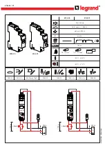
List of Models

Note: 1.

Models with a 24-VDC power supply have a non-isolated power supply.
The inputs and power supply are connected internally, so a malfunction may occur due to an unwanted current path if the inputs and 
power supply are connected to the same line. 
If an unwanted current path exists, use a K8AB AC Power Supply or isolate with an external power supply.

2.

The K8AB-AS3 is designed to be used in combination with an OMRON K8AC-CT200L Current Transformer (CT). (Direct input is not 
possible.)

Accessory (Order Separately)

OMRON CT

Other CTs

Ratings and Specifications

Input Range

Single-phase Current Relay

Measuring current

Supply voltage

Model

2 to 20 mA AC/DC, 
10 to 100 mA AC/DC, 
50 to 500 mA AC/DC

24 VDC, not insulated

K8AB-AS1 24 VDC (See note 1.)

24 VAC, insulated

K8AB-AS1 24 VAC

100-115 VAC, insulated

K8AB-AS1 100-115 VAC

200-230 VAC, insulated

K8AB-AS1 200-230 VAC

0.1 to 1 A AC/DC, 
0.5 to 5 A AC/DC, 
0.8 to 8 A AC/DC

24 VDC, not insulated

K8AB-AS2 24 VDC (See note 1.)

24 VAC, insulated

K8AB-AS2 24 VAC

100-115 VAC, insulated

K8AB-AS2 100-115 VAC

200-230 VAC, insulated

K8AB-AS2 200-230 VAC

10 to 100 A AC, 
20 to 200 A AC 
(See note 2.)

24 VDC, not insulated

K8AB-AS3 24 VDC (See note 1.)

24 VAC, insulated

K8AB-AS3 24 VAC

100-115 VAC, insulated

K8AB-AS3 100-115 VAC

200-230 VAC, insulated

K8AB-AS3 200-230 VAC

Current Transformer

Input range

Applicable Relay

Model

10 to 100 A AC, 
20 to 200 A AC

K8AB-AS3

K8AC-CT200L

CT current on secondary side

Applicable Relay

0 to 1 A AC,
0 to 5 A AC

K8AB-AS2

Model

Range

Connection terminal

Input impedance

Overload capacity

K8AB-AS1

2 to 20 mA AC/DC

I1-COM

Approx. 5 

120% max. input continuous
150% max. input for 1 s

10 to 100 mA AC/DC I2-COM

Approx. 1 

50 to 500 mA AC/DC I3-COM

Approx. 0.2 

K8AB-AS2

0.1 to 1 A AC/DC

I1-COM

Approx. 0.12 

 (load: 0.5 VA)

0.5 to 5 A AC/DC

I2-COM

Approx. 0.02 

 (load: 1.5 VA)

0.8 to 8 A AC/DC

I3-COM

Approx. 0.02 

 (load: 3 VA)

K8AB-AS3

10 to 100 A AC

I2-COM

Uses commercial CT

120% max. input continuous
200% max. input for 30 s
600% max. input for 1 s

20 to 200 A AC

I3-COM

Uses commercial CT

Summary of Contents for K8AB-AS

Page 1: ...Commercial CT input signal 0 to 1 A 0 to 5 A supported Output status can be monitored using LED indicator Model Number Structure Model Number Legend 1 Basic Model K8AB Measuring and Monitoring Relays...

Page 2: ...1 to 1 A AC DC 0 5 to 5 A AC DC 0 8 to 8 A AC DC 24 VDC not insulated K8AB AS2 24 VDC See note 1 24 VAC insulated K8AB AS2 24 VAC 100 115 VAC insulated K8AB AS2 100 115 VAC 200 230 VAC insulated K8AB...

Page 3: ...ely 30 or more of the set value Note Enabled only for overcurrent operation Indicators Power PWR Green Relay output RY Yellow Alarm outputs ALM Red Input impedance Refer to the Input Range on the prev...

Page 4: ...luence Operating value Based on ambient humidity of 65 25 to 80 5 max Operating time Based on ambient room humidity 25 to 80 10 max Influence of power supply voltage Operating value 5 max Operating ti...

Page 5: ...current path if the inputs and power supply are connected to the same line T LOCK Hysteresis 5 to 50 of operating value Lit Flashing T Operating time 0 1 to 30 s Lock Startup lock time 0 to 30 s Oper...

Page 6: ...K Alarm indicator Terminal block See notes 1 and 2 Terminal block See notes 1 and 2 Item Meaning Power indicator PWR Green Lit when power is being supplied Relay status indicator RY Yellow Lit when re...

Page 7: ...method relay drive method and operating mode are set using the DIP switch located on the bottom of the Unit K8AB AS does not use SW1 Setting Method 1 Setting Current The current knob SV is used to se...

Page 8: ...for the set period and then stay lit 4 Startup Lock Time The startup lock time is set using the startup lock time knob LOCK The startup lock time can be set to between 0 and 30 s Turn the knob while t...

Page 9: ...s 2 Make sure to use setting values appropriate for the controlled object Failure to do so can cause unintended operation and may result in accident or corruption of the product 3 Do not use thinner o...

Page 10: ...ply are connected internally so the K8AB AS will not operate normally if an unwanted current path exists If an unwanted current path exists use a K8AB model with an AC power supply or use an isolated...

Page 11: ...rating value 25 operating time 0 1 s startup lock timer 0 1 to 30 s set according to the duration of the startup current The K8AB AS3 can be set to between 10 to 100 of the rated current 10 A to 100 A...

Page 12: ...ice of the product on which liability is asserted IN NO EVENT SHALL OMRON BE RESPONSIBLE FOR WARRANTY REPAIR OR OTHER CLAIMS REGARDING THE PRODUCTS UNLESS OMRON S ANALYSIS CONFIRMS THAT THE PRODUCTS W...

Reviews: