


3.15 Explanation of I/O Signals
42
3.15 Explanation of I/O Signals
Pulse train references are given to control the position of the servomotor. The following pulse train forms
from the host controller are supported.
• Line driver output
• +24-V open-collector output
• +12-V open-collector output
• +5-V open-collector output
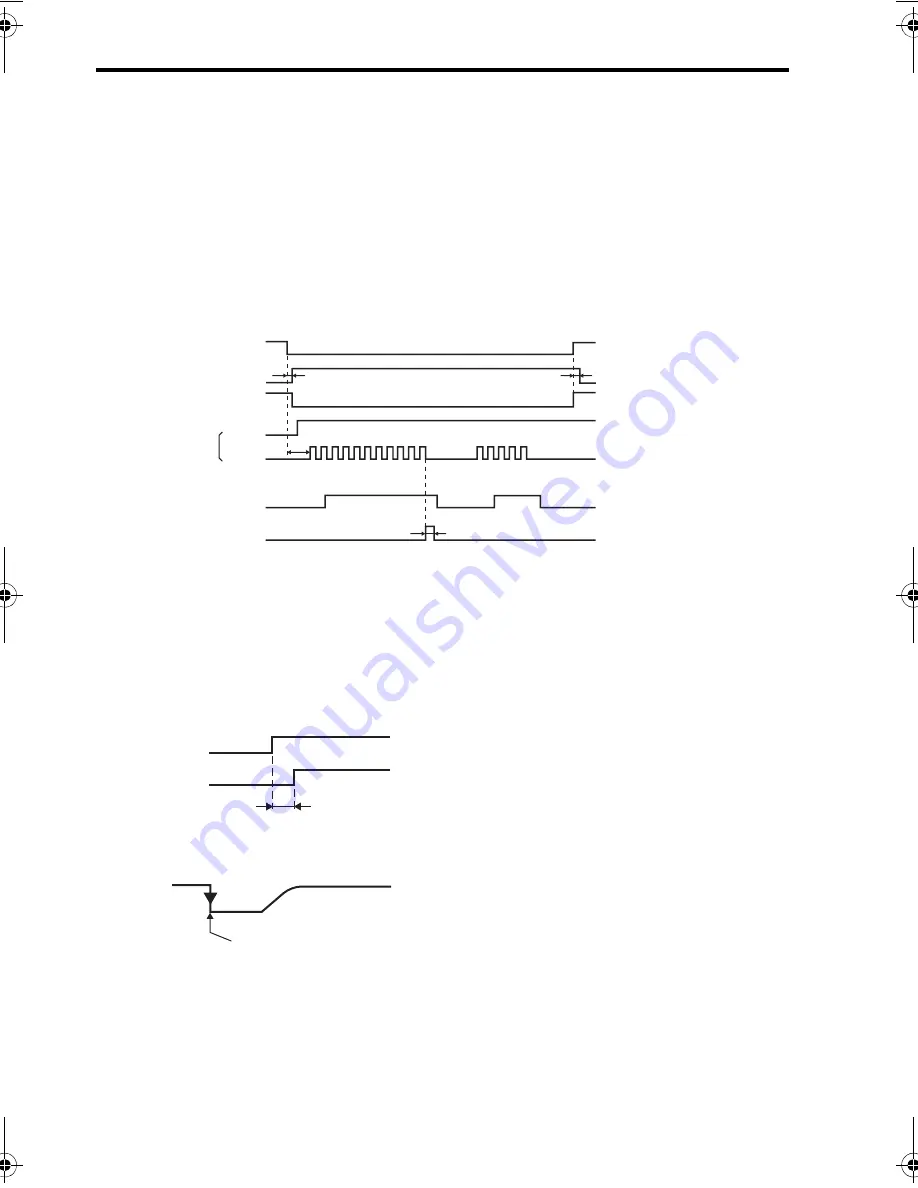
I/O Signal Timing Examples
* 1. The interval from when the servo ON signal is turned ON until the reference pulse is input must be at
least 40 ms, or the reference pulse may not be received by the SERVOPACK. If a motor with a brake is
in used, more time will be required to release the brake. Therefore, provide an interval of at least 100
ms.
* 2. The error counter clear signal must be ON for at least 20
μ
s. If the reference pulse is stopped when the
clear signal is turned ON, the motor will stop at that position.
* 3. The lag time for the brake is 100 ms. Use a relay for brakes with an operating time of 30 ms or less.
Note: 1. The maximum lag time from the time that the error or fault is detected until the time that the alarm
signal is turned ON is 2 ms.
2. If using the phase-C output signal, use an edge when the signal changes from OFF to ON at the
start, so that the wave form will rise after a set time lag.
Servo ON (/S-ON)
Positioning completed (/COIN)
Clear (CLR)
Motor ON
Brake (/BK)
Sign + pulse train
Motor ON
Brake released
L
H
H
ON
ON
ON
t4
t3
t2
t1
(SIGN)
(PULS)
t1: Approx. 40 ms
t2: Approx. 130 ms*
3
t3
≥
40 ms*
1
(Motor with brake: 100 ms)
t4
≥
20
μ
s*
2
2ms max.
Alarm detection
ALM
PCO
TOEP_C710806_01A_0_0.book Seite 42 Montag, 2. Juli 2007 4:24 16