6
.
Serial Communications Settings
9
Cable Wiring
6.2.
Refer to
Section 3 Installation and Wiring
of the
CJ-series Serial Communications Units
Operation Manual for NJ-series CPU Unit
(Cat. No. W494) for details on cable wiring.
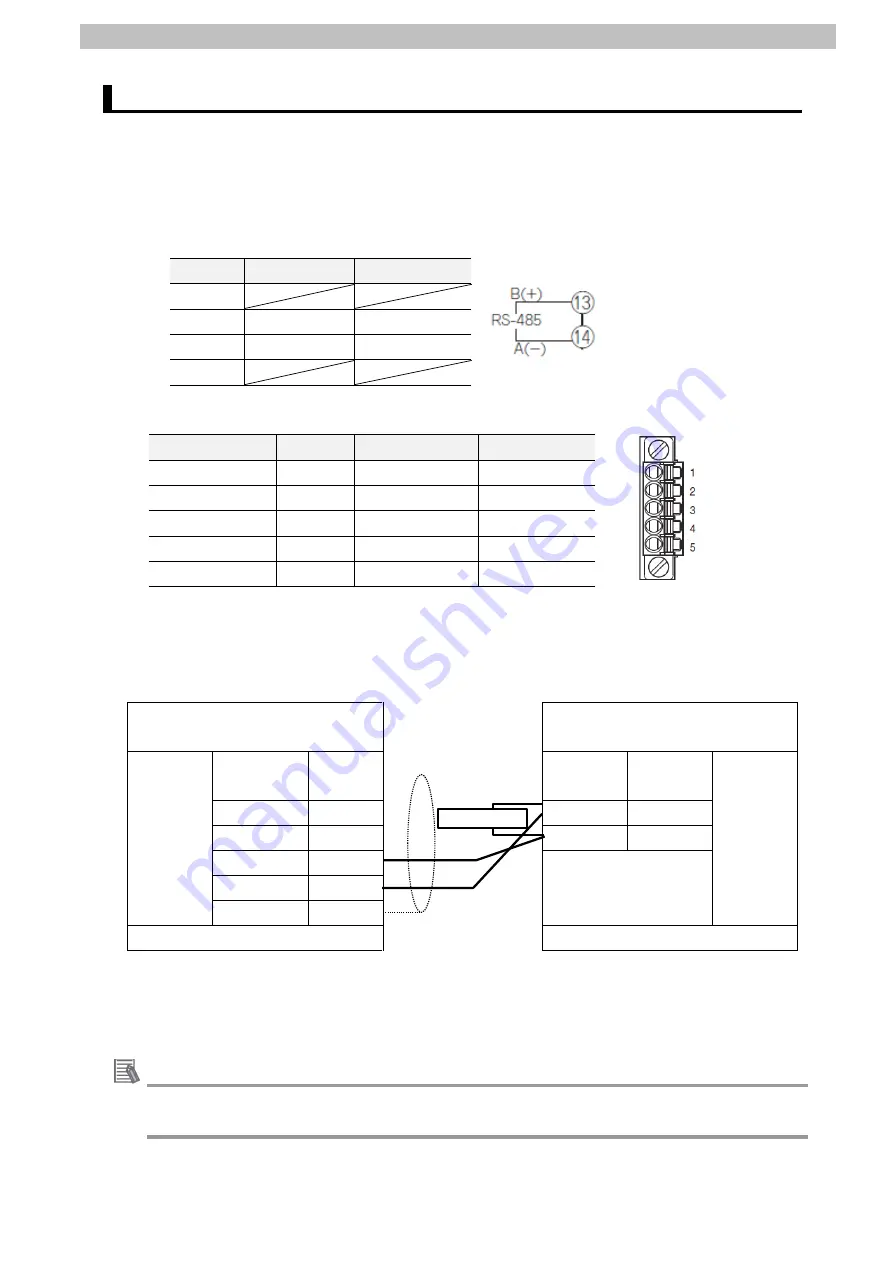
Check the connector configurations and pin assignments before wiring.
■Conn
ector configuration and pin assignment
Digital Temperature Controller (E5CD) applicable connector: Terminal block
Pin No.
Signal name
Input/Output
1-12
13
B(+)
Input/Output
14
A(-)
Input/Output
15-18
Serial Communications Unit (CJ1W-SCU42) applicable connector: Terminal block
Pin No.
Symbol
Signal name
Input/Output
1 (See note 1.)
RDA
Receive data -
Input
2 (See note 1.)
RDB
Receive data +
Input
3 (See note 1.)
SDA
Send data -
Output
4 (See note 1.)
SDB
Send data +
Output
5 (See note 2.)
FG
Shield
-
Note 1: For 2-wire connection, use either pins 1 and 2 or pins 3 and 4.
2: Pin 5 (Shield) is connected to the GR terminal on the Power Supply Unit though the
Serial Communications Unit. The cable shield can thus be grounded if you ground the
GR terminal of the Power Supply Unit.
■Cab
le and pin assignment
Serial Communications
Unit (CJ1W-SCU42)
Digital Temperature Controller
(E5CD)
RS-422A/
485
interface
Signal
name
Pin No.
Terminal
No.
Signal
name
RS-485
interface
RDA-
1
13
B(+)
RDB+
2
14
A(-)
SDA-
3
SDB+
4
FG
5
Terminal block
Terminal block
Connect 120 Ω (1/2 W) terminating resistance
between B(+) and A(-) of the Digital Temperature
Controller that is connected at the end of the
network.
Additional Information
For information on the connector configurations and pin assignments of the other models,
refer to their respective manuals.
Terminating resistance


