background image

7

Serial Communications Connection Procedure 


16 

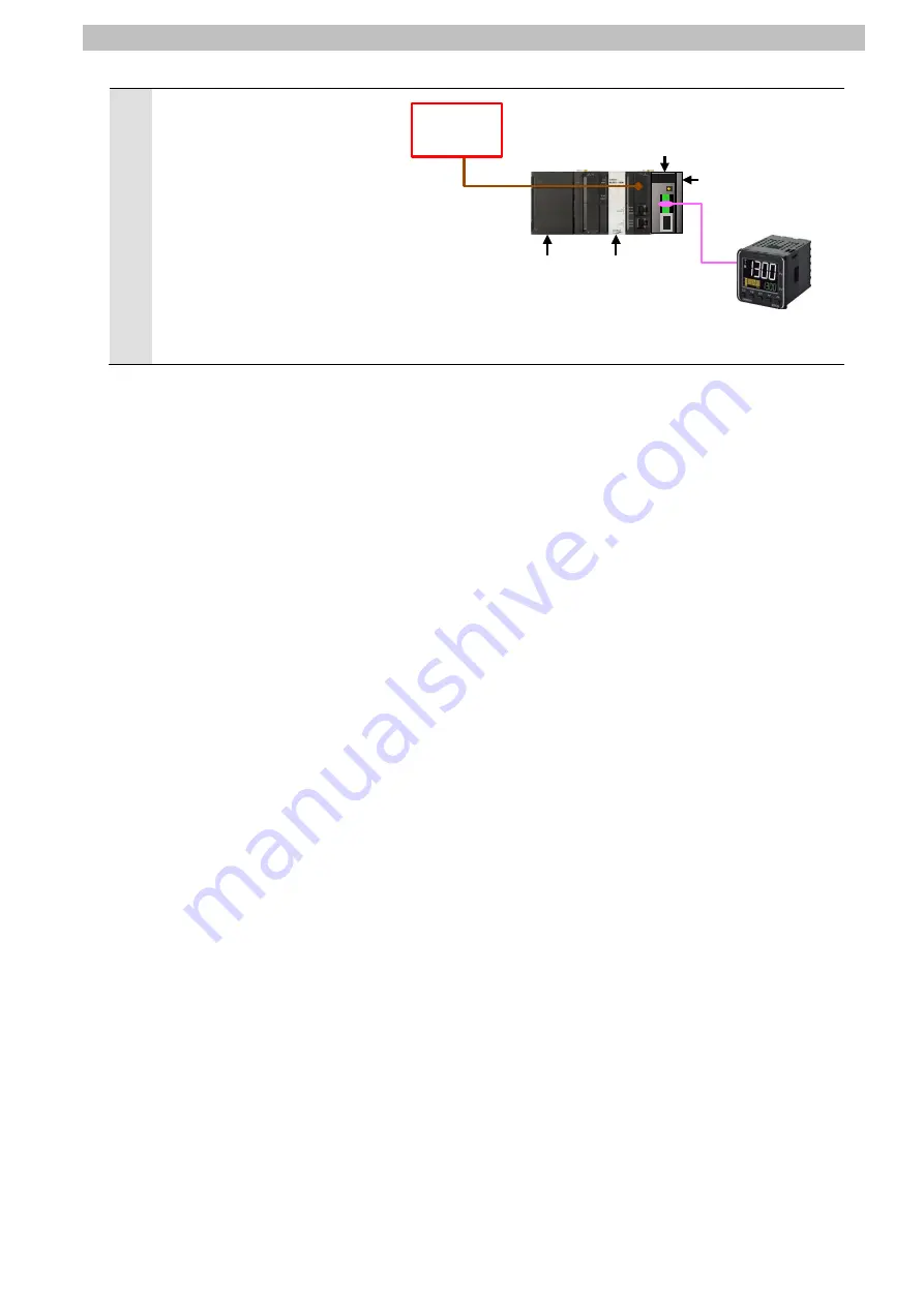
Connect Serial Communications 

Unit to Controller as shown on 

the right.   


Connect Digital Temperature 

Controller and Port 1 on Serial 

Communications Unit with the 

serial cable. 


Connect Personal computer and 

Controller with a USB cable.   


Serial cable 
(RS-485) 

Serial Communications Unit 

USB 
Cable


Controller 

End Cover 

Power Supply Unit 

CPU Unit 

Personal 
computer 

Summary of Contents for E5*D series

Page 1: ...Machine Automation Controller NJ series General purpose Serial Connection Guide RS 485 CompoWay F OMRON Corporation Digital Temprature Controller E5 D E5 C E5 C T P520 E1 02 ...

Page 2: ...ion in the USA and other countries EtherCAT is registered trademark and patented technology licensed by Beckhoff Automation GmbH Germany Sysmac is a trademark or registered trademark of OMRON Corporation in Japan and other countries for OMRON factory automation products Company names and product names in this guide are the trademarks or registered trademarks of their respective companies ...

Page 3: ...ommunications Connection Procedure 10 Work Flow 10 7 1 Digital Temperature Controller Setup 11 7 2 Controller Setup 15 7 3 Serial Communication Status Check 30 7 4 8 Initialization Method 32 Initializing a Controller 32 8 1 Initializing a Digital Temperature Controller 33 8 2 9 Program 34 Overview 34 9 1 Destination Device Command 40 9 2 Error Detection Processing 43 9 3 Variables 44 9 4 ST Progra...

Page 4: ... W494 CJ1W SCU 2 CJ series Serial Communications Units Operation Manual for NJ series CPU Unit H225 E5 D Digital Temperature Controllers Communications Manual H224 E5 D Digital Temperature Controllers User s Manual H175 E5 C Digital Temperature Controllers Communications Manual H174 E5 C Digital Temperature Controllers User s Manual H186 E5 C T Digital Temperature Controllers Programmable Type Com...

Page 5: ...d in this guide is current as of March 2018 It is subject to change for improvement without notice The following notations are used in this guide Indicates a potentially hazardous situation which if not avoided may result in minor or moderate injury or may result in serious injury or death Additionally there may be significant property damage Indicates a potentially hazardous situation which if no...

Page 6: ...Temperature Controller Sending command data Executing the command Receiving response data and storing in memory Returning response data Prepare the Sysmac Studio project file with a latest version beforehand To obtain the Sysmac Studio project file contact your OMRON representative Name File name Version Sysmac Studio project file extension csm2 P520_NJ_CWF485_OMRON_E5CD_V100 csm2 Ver 1 00 Hereina...

Page 7: ...CU 2 OMRON Digital Temperature Controller E5CD 2 M 002 E5CD 2 M 004 E5ED 4 M 004 E5ED 4 M 008 E5ED 4 M 022 E5CC M 002 E5CC M 003 E5CC M 004 E5AC SM 004 E5AC SM 008 E5AC SM 009 E5AC SM 012 E5AC SM 014 E5EC M 004 E5EC M 008 E5EC M 009 E5EC M 012 E5EC M 014 E5DC M 002 E5DC M 015 E5GC M 015 E5CC T 3 SM 002 E5CC T 3 SM 003 E5CC T 3 SM 004 E5AC T 4 SM 004 E5AC T 4 SM 008 E5AC T 4 SM 020 E5AC T 4 SM 022 ...

Page 8: ...versions listed in 5 2 To use the above devices with models not listed in 5 2 or versions higher than those listed in 5 2 check the differences in the specifications by referring to the manuals before operating the devices Additional Information This guide describes the procedures for establishing the network connection It does not provide information on operation installation wiring method device...

Page 9: ...rehand To obtain the project file contact your OMRON representative Precautions for Correct Use Update Sysmac Studio to the version specified in this Clause 5 2 or to a higher version If you use a version higher than the one specified the procedures and related screenshots described in Section 7 and the subsequent sections may not be applicable In that case use the equivalent procedures described ...

Page 10: ...ommunications Units Operation Manual for NJ series CPU Unit Cat No W494 Additional Information The system configuration in this guide uses USB for the connection between the personal computer and the Controller For information on how to install the USB driver refer to A 1 Driver Installation for Direct USB Cable Connection of the Sysmac Studio Version 1 Operation Manual Cat No W504 ...

Page 11: ... ON TERM ON 2 wire or 4 wire 2 wire WIRE 2 2 wire fixed Serial communications mode Serial Gateway Data length transmission character 7 bits default 7 bits default Stop bits 2 bits default 2 bits default Parity parity bit Even default Even default Baud rate 9 600 bps default 9 600 bps default Communications method CompoWay F default Send data wait time 20 ms default Precautions for Correct Use The ...

Page 12: ... Output 4 See note 1 SDB Send data Output 5 See note 2 FG Shield Note 1 For 2 wire connection use either pins 1 and 2 or pins 3 and 4 2 Pin 5 Shield is connected to the GR terminal on the Power Supply Unit though the Serial Communications Unit The cable shield can thus be grounded if you ground the GR terminal of the Power Supply Unit Cable and pin assignment Serial Communications Unit CJ1W SCU42 ...

Page 13: ...mperature Controller 7 3 Controller Setup Set up the Controller 7 3 1 Hardware Settings Set the hardware switches on the Serial Communications Unit and connect the cables 7 3 2 Starting Sysmac Studio and Importing the Project File Start Sysmac Studio and import the project file 7 3 3 Checking the Parameters and Building Programs Check the parameters of the Serial Communications Unit execute the pr...

Page 14: ...re described in this guide If you use the parameters in Adjustment Level that is specific to each of the models refer to their respective manuals 2 Check the positions of each of the keys No 1 and No 2 displays and Operation indicators In this guide the keys are described as follows L Level Key M Mode Key U Up Key D Down Key 3 Turn ON Digital Temperature Controller 4 The current temperature is dis...

Page 15: ...to change the parameter Press the M Mode Key Setting value CWF Mod default CWF CWF CompoWay F Mod Modbus RTU M Mode Key 7 u no Communications Unit No is displayed Check that Communications Unit No is 1 If the setting value is different change it in the same way as step 6 Press the M Mode Key Setting value 0 to 99 default 1 M Mode Key 8 bps Communications Baud Rate is displayed Check that Communica...

Page 16: ...lue is different change it in the same way as step 6 Press the M Mode Key Setting value 1 or 2 bits default 2 M Mode Key 11 prty Communications Parity is displayed Check that Communications Parity is EVEN If the setting value is different change it in the same way as step 6 Press the M Mode Key Setting value NONE EVEN or ODD default EVEN M Mode Key 12 sdwt Send Data Wait Time is displayed Check th...

Page 17: ...Procedure 14 13 in t Initial Setting Level is displayed Press the L Level Key for at least 1 second L Level Key for at least 1 second 14 The display returns to Operation Level as shown in step 4 15 Turn OFF Digital Temperature Controller ...

Page 18: ...may not be applicable 1 Make sure that Controller is powered OFF 2 Check the positions of the hardware switches and Port 1 on the front panel of Serial Communications Unit by referring to the figure on the right 3 Set Unit number switch to 0 The unit number is set to 0 as the factory default setting 4 Set Terminating resistance ON OFF switch to ON Terminating resistance ON 5 Set 2 wire or 4 wire s...

Page 19: ... shown on the right Connect Digital Temperature Controller and Port 1 on Serial Communications Unit with the serial cable Connect Personal computer and Controller with a USB cable Serial cable RS 485 Serial Communications Unit USB Cable Controller End Cover Power Supply Unit CPU Unit Personal computer ...

Page 20: ...le Install Sysmac Studio and the USB driver on your personal computer beforehand 1 Start Sysmac Studio If the User Account Control Dialog Box is displayed at start make a selection to start Sysmac Studio 2 Click Import 3 The Import file Dialog Box is displayed Select P520_NJ_CWF485_ OMRON_E5CD_V100 csm2 and click Open Obtain the project file from OMRON ...

Page 21: ...anes are displayed in this window Left Multiview Explorer Top right Toolbox Bottom right Controller Status Pane Top middle Edit Pane The following tabs are displayed in the bottom middle of this window Output Tab Page Build Tab Page Controller Status Pane Toolbox Edit Pane Multiview Explorer Output Tab Page Build Tab Page ...

Page 22: ...p in the Multiview Explorer 2 The CPU Expansion Racks Tab Page is displayed in the Edit Pane Select Serial Communications Unit as shown on the right The setting values of CJ1W SCU42 are displayed Check that the device name is J01 and that the unit No is 0 If the setting values are different from the above change the values Click Edit Special Unit Settings 3 The 0 Unit 0 CJ1W SCU42 J01 Tab Page is ...

Page 23: ...es are different select the values from the pull down list After changing the values click Apply 5 Double click I O Map under Configurations and Setup in the Multiview Explorer The I O Map Tab Page is displayed and then the parameters of Serial Communications Unit are listed 6 Check that the variable names in the Variable Column start with J01 and that Global Variables is set for each of them in t...

Page 24: ...utton Check that Program0 is set in the Primary Task Field and that Run is set as the initial status 9 Select Check All Programs from the Project Menu 10 The Build Tab Page is displayed Check that 0 Errors and 0 Warnings are displayed 11 Select Rebuild Controller from the Project Menu 12 A confirmation dialog box is displayed Check the contents and click Yes 13 Check that 0 Errors and 0 Warnings a...

Page 25: ... Studio The devices or machines may perform unexpected operation regardless of the operating mode of the CPU Unit Always confirm safety before you reset the Controller or any components 1 Turn ON Controller and Digital Temperature Controller 2 Select Change Device from the Controller Menu 3 The Change Device Dialog Box is displayed Check that the Device and Version Fields are set as shown on the r...

Page 26: ... The contents of the dialog box vary depending on the status of Controller Check the contents and click on an appropriate button to proceed with the processing 7 When an online connection is established a yellow line is displayed under the toolbar Additional Information For details on the online connections to the Controller refer to Section 6 Online Connections to a Controller of the Sysmac Studi...

Page 27: ... To Controller After executing Transfer To Controller the Sysmac Studio data is transferred to Controller and the data is synchronized 10 A confirmation dialog box is displayed Confirm that there is no problem and click Yes A screen is displayed stating Synchronizing A confirmation dialog box is displayed Confirm that there is no problem and click No Do not return to RUN mode ...

Page 28: ...ng The Synchronization process successfully finished Confirm that there is no problem and click Close When the Sysmac Studio project data coincides with the Controller data a message is displayed stating The synchronization process successfully finished If the synchronization fails check the wiring and repeat from step 1 Precautions for Correct Use Always confirm safety before you reset the Contro...

Page 29: ... RUN Mode In this case select Mode PROGRAM Mode from the Controller Menu to change to PROGRAM mode and then perform this step 13 A confirmation dialog box is displayed Check the contents and click Yes 14 A confirmation dialog box is displayed Check the contents and click Yes 15 The Controller is reset and Sysmac Studio goes offline The yellow line under the toolbar disappears ...

Page 30: ...low line is displayed under the toolbar 3 Select Mode PROGRAM Mode from the Controller Menu 4 A confirmation dialog box is displayed Confirm that there is no problem and click Yes 5 PROGRAM mode is displayed in the Controller Status Pane 6 Double click CPU Expansion Racks under Configurations and Setup in the Multiview Explorer Select Serial Communications Unit displayed on the CPU Rack configurat...

Page 31: ...ox is displayed Check the contents and click Yes A dialog box is displayed indicating that transferring is being performed After that the dialog box on the right is displayed Check the contents and click Yes 9 The Port Selection Dialog Box is displayed Select All ports and click OK 10 A confirmation dialog box is displayed Check the contents and click OK ...

Page 32: ...ations Connection Procedure 29 11 Select Port1 Serial Gateway Settings from the pull down list of Parameter group to show Click Compare 12 Check that mismatch is not shown within the red oval in the figure on the right ...

Page 33: ... safety before you change the variable values on a Watch Tab Page when Sysmac Studio is online with the CPU Unit Precautions for Correct Use Check that the serial cable is connected before performing the following procedure If not turn OFF both devices and then connect the serial cable 7 4 1 Checking Received Data Check that correct data is written to the variables of the Controller in Sysmac Stud...

Page 34: ...ue of Input_Start changes to True and the communications processing starts 9 Check received data on the Watch Tab Page of Sysmac Studio The example on the right shows that the online values of Output_recvByteSize the number of data bytes and Output_recvCWFdata string data are 28 bytes and 01 00 00 0503 0000 E5CD RX2A6 00D9 respectively The response data varies depending on the device used Response...

Page 35: ... of a Controller it is necessary to initialize a Serial Communications Unit and a CPU Unit Change the operating mode of the Controller to PROGRAM mode before the initialization 8 1 1 Serial Communications Unit To initialize the settings of a Serial Communications Unit select the displayed Serial Communications Unit CJ1W SCU42 and click Edit Special Unit Settings on the CPU Expansion Racks Tab Page...

Page 36: ...Studio The Clear All Memory Dialog Box is displayed Check the contents and click OK Initializing a Digital Temperature Controller 8 2 To initialize the settings of a Digital Temperature Controller refer to Parameter Initialization in 6 8 Advanced Function Setting Level of the Digital Temperature Controllers User s Manual Cat No H224 H174 H185 ...

Page 37: ...ocessing means a normal end of communications via CompoWay F An error end means an error end of communications via CompoWay F and an error of the Destination Device identified in the response data from the Destination Device Here the prefix 10 possible to omit is added to decimal data and the prefix 16 is added to hexadecimal data when it is necessary to distinguish between decimal and hexadecimal...

Page 38: ...es the command by receiving the command data from the Controller and returns response data to the Controller 4 The Controller receives the response data from the Digital Temperature Controller and stores in the specified variable Controller RS 485 Digital Temperature Controller CPU Unit SCU ST program IF THEN ELSE End_IF SendCmd Local_cmddata Command data setting area Serial Gateway function 1 Exe...

Page 39: ...ending receiving a message Additional Information For details on the SendCmd instruction refer to Serial Communications Instructions in Section 2 Instruction Descriptions of the NJ NX series Instructions Reference Manual Cat No W502 SendCmd instruction Name Function block Description Send Command SendCmd The SendCmd instruction uses a Serial Gateway and sends a command to SCU SendCmd instruction a...

Page 40: ... destination serial port number Variable Setting item Data type Description CommPort Destination serial port _ePORT _NONE The destination is not a serial port in Host Link Mode Set _NONE to specify the serial port unit address as a destination unit address CmdSize Command data size The following table shows the variable that stores the number of command data bytes send data Variable Setting item D...

Page 41: ...e storage array RespDat is stored in the BYTE array variable Local_recvdata The data is then converted into the STRING array variable Output_recvCWFdata and is checked Response storage array 0 1 2 3 4 5 6 7 8 9 10 11 12 13 14 15 16 17 28 03 aa bb AA BB CC DD cc dd FF GG HH II ee ff gg hh CompoWay F command Comm and end code Node No Sub address End code Command Response Text MRC SRC MRES SRES The s...

Page 42: ...mand Node No Subaddress SID Command MRC SRC Text SCU Destination Device send data STX Node No Sub address SID Command Text ETX BCC 16 02 MRC SRC 16 03 Relationship between receive response SendCmd instruction operand and receive message Destination Device SCU receive data STX Node No Sub address End code Command Response Text ETX BCC 16 02 MRC SRC MRES SRES 16 03 Local_re cvdata 0 1 2 3 4 5 6 7 8 ...

Page 43: ...etting item Data type Setting value DstNetAdr Destination network address _sDNET_ADR NetNo Network address USINT 16 00 Fixed Local network NodeNo Node address USINT 16 00 Fixed Within local controller UnitNo Unit address BYTE 16 80 Unit number 0 Port number 1 CommPort Destination serial port Variable Setting item Data type Setting value CommPort Destination serial port _ePORT _NONE Fixed CmdSize C...

Page 44: ...ay CmsDat Variable Data type Data Local_cmdCWFdata STRING 256 CONCAT NodeNo SubAddress SID MRCSRC SendText SendCmd instruction receive data RespDat Response storage array Variable Storing item Data type Storing value RespDat Response storage array ARRAY 0 255 OF BYTE Element number 0 CompoWay F command BYTE 16 28 Fixed Same as CmdDat 0 1 BYTE 16 03 Fixed Same as CmdDat 1 2 Command end code BYTE 16...

Page 45: ...ly removed from the receive message by the SCU Data not used is moved forward 02 30 31 30 30 30 30 30 35 30 33 30 30 30 30 STX Node No Subaddress End code Command MRC Command SRC Response MRES Response SRES Model number Buffer size 03 ETX BCC Receive message at error operation This is the response frame of the error message received by the Controller from the Destination Device Except for STX ETX ...

Page 46: ...racter corruption or unmatched baud rate setting the transmission error status J01_P1_TransErrSta that is the allocated variable area of the SCU will be stored in the output variable to show the communication error status 2 Errors in the Destination Device Destination Device errors Destination Device errors include a command error a parameter error and an execution failure in the Destination Devic...

Page 47: ...d instruction Normal end 16 00000000 Output_TransErrCode WORD Transmission error status when a communication error occurs Storage area of J01_P1_TransErrSta Normal end 16 0000 Output_CWFErrCode1 WORD An area that stores the Destination Device end code when a Destination Device error occurs Normal end 16 0000 Output_CWFErrCode2 WORD An area that stores the response code when a Destination Device er...

Page 48: ...ons processing in progress Local_Done BOOL Communications processing status flag Communications processing normal end Local_Error BOOL Communications processing status flag Communications processing error end Local_State DINT Processing number Local_ExecFlgs BOOL Communications instruction execution flag Local_DstNetAdr _sDNET_ADR Destination address for SendCmd instruction setting Local_CommPort ...

Page 49: ...n execution flag 2 3 Initializing the error code storage areas 2 4 Setting the SendCmd instruction control data 2 5 Setting the send variables 2 6 Initializing the receive data storage areas 2 7 Initialization setting end processing The receive data storage areas and the error code storage areas are initialized The parameters and send data are set for the SendCmd instruction CompoWay F 3 CompoWay ...

Page 50: ...am used in this guide is shown below The send data command data setting to the Destination Device is boxed in red in this program list Program Program0 General purpose serial communications connection check program 1 Communications processing ...

Page 51: ...9 Program 48 2 Initialization processing ...

Page 52: ...9 Program 49 3 CompoWay F communications processing ...

Page 53: ...9 Program 50 4 Processing number error process ...

Page 54: ...put_Start Local_Status Busy Output_recvCWFdata Error Error response Local_Status Done Local_Status Error Output for 1 period 1 Output_CmdErrorID 16 FFFF 16 xxxx 16 FFFF 16 FFFF 16 0000 16 FFFF 16 0000 Output_TransErrorCode 16 FFFF 16 xxxx 16 FFFF 16 FFFF 16 1000 16 FFFF 16 1000 Output_CWFErrCode1 and 2 16 FFFF 16 FFFF 16 xxxx 16 FFFF 16 xxxx 1 If Input_Start changes from TRUE to FALSE during the e...

Page 55: ...e data area range 16 0407 The results of instruction processing exceeded the data area range of the output parameter 16 0800 An error occurred when a FINS command was sent or received Detailed information is stored in Output_CmdErrorIDEx 16 0801 The port is being used Additional Information For details on errors refer to A 3 Error Code Details of the NJ NX series Instructions Reference Manual Cat ...

Page 56: ... at a transmission error Bit Description 15 1 Transmission error 0 No transmission error 14 Not used 13 1 SendCmd instruction error 0 Normal 12 1 Destination Device error 0 Normal 9 to 11 Not used 8 1 Processing number error 0 Normal 7 1 FCS check error 0 FCS check normal 6 Not used 5 1 Timeout error 0 Normal 4 1 Overrun error 0 Normal 3 1 Framing error 0 Normal 2 1 Parity error 0 Normal 0 and 1 N...

Page 57: ...a is 1 does not match the set value of the communications parity bit 2 11 Framing error Stop bit is 0 1 12 Overrun error An attempt was made to transfer new data when the reception data buffer was already full 3 13 BCC error The calculated BCC value is different from the received BCC value 5 14 Format error The command text contains characters other than 0 to 9 and A to F There was no SID and comm...

Page 58: ...ge error 5 1104 End address out of range error 6 1003 Number of elements data mismatch 7 110B Response too long 8 1100 Parameter error 9 3003 Read only error 10 2203 Operation error 11 Additional Information For details and troubleshooting on the Destination Device errors refer to the Digital Temperature Controllers User s Manual Cat No H224 H174 H185 and the Digital Temperature Controllers Commun...

Page 59: ...y Revision code Date of revision Description of revision 01 January 2013 First edition 02 June 2018 Added the model numbers of the Digital Temperature Controller Revision and changes associated with upgrades of the Controller and Sysmac Studio ...

Page 60: ...2013 2018 0618 0113 P E1 0 ...

Reviews: