background image

Proximity Sensors Technical Guide

Design

Sensing Object Material

The sensing distance varies greatly depending on the material of the 
sensing object. Study the engineering data for the influence of 
sensing object material and size and select a distance with sufficient 
leeway.

In general, if the 
sensing object is a non-
magnetic metal (for 
example, aluminum), 
the sensing distance 
decreases.

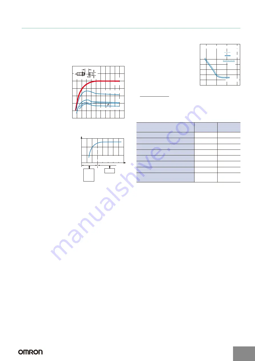
Size of Sensing Object

In general, if the object is smaller 
than the standard sensing 
object, the sensing distance 
decreases.

Design the setup for an object 
size that is the same or greater 
than the standard sensing 
object size from the graphs 
showing the sensing object 
size and sensing distance.

When the size of the standard 
sensing object is the same or 
less than the size of the 
standard sensing object, 
select a sensing distance with 
sufficient leeway.

Thickness of Sensing Object

The thickness of ferrous metals 
(iron, nickel, etc.) must be 1 mm 
or greater.

When the coating thickness is 
0.01 mm or less, a sensing 
distance equivalent to a 
magnetic body can be obtained.
When the coating is extremely 
thin and is not conductive, such 
as a vacuum deposited film, 
detection is not possible.

Influence of Plating  If the 
sensing object is plated, the 
sensing distance will change 
(see the table below).

Effect of Plating (Typical)
(Reference values: Percent of non-plated sensing distance)

Mutual Interference

Mutual interference refers to a state where a Sensor is affected by 
magnetism (or static capacitance) from an adjacent Sensor and the 
output is unstable.

One means of avoiding interference when mounting Proximity 
Sensors close together is to alternate Sensors with different 
frequencies. The model tables indicate whether different 
frequencies are available. Please refer to the tables.

When Proximity Sensors with the same frequency are mounted 
together in a line or face-to-face, they must be separated by a 
minimum distance. For details, refer to 

Mutual Interference

 in the 

Safety Precautions

 for individual Sensors.

Power Reset Time

A Sensor is ready for detection within 100 ms after turning ON the 
power. If the load and Sensor are connected to separate power 
supplies, design the system so that the Sensor power turns ON first.

Aluminum

Copper

Brass

Stainless steel

Steel

(SPCC)

0

5 10 15 20 25 30 35 40 45 50 55

Side length (one side) of sensing object: d (mm)

14

12

10

8

6

4

2

X

d

t=1mm

Sens

ing d

istance X (mm)

Example: E2-X10D

@

Stability

Side length (one side) 
of sensing object: d (mm)

Sens

ing d

istance X (mm)

Standard
sensing
object

Sensing
distance
becomes
short

Thickness and base material of 
plating

Steel

Brass

No plating

100

100

Zn 5 to 15 

μ

m

90 to 120

95 to 105

Cd 5 to 15 

μ

m

100 to 110

95 to 105

Ag 5 to 15 

μ

m

60 to 90

85 to 100

Cu 10 to 20 

μ

m

70 to 95

95 to 105

Cu 5 to 15 

μ

m

-

95 to 105

Cu (5 to 10 

μ

m) + Ni (10 to 20 

μ

m)

70 to 95

-

Cu (5 to 10 

μ

m) + Ni (10 

μ

m) 

+ Cr (0.3 

μ

m)

75 to 95

-

Aluminum

Steel

0 0.01

0.1

1

10

Thickness of sensing object: t (mm)

10

8

6

4

2

Sens

ing d

istance X (mm)

Reset
Operate

Sensing object shape: Square

d=30mm

http://www.ia.omron.com/

C-3

(c)Copyright OMRON Corporation 2007   All Rights Reserved. 

Summary of Contents for E2EC -

Page 1: ...e also available The model numbers are E2EC 5 example E2EC CR8D15 DC 3 Wire Models Models with different frequencies are also available The model numbers are E2EC 5 example E2EC CR5D15 Accessories Ord...

Page 2: ...proaching D1 Models NO D2 Models NC Refer to the timing charts under I O Circuit Diagrams on page 5 for details NO Refer to the timing charts under I O Circuit Diagrams on page 5 for details Protectio...

Page 3: ...nce X mm Distance Y mm Sensing Head Y X 4 3 2 1 0 3 1 2 0 1 2 3 4 4 Distance X mm Distance Y mm Sensing Head Y X 6 5 4 3 2 1 0 4 2 0 2 4 Distance Y mm Distance X mm Sensing Head Y X 0 6 0 5 0 4 0 3 0...

Page 4: ...er Brass Distance X mm Side length of sensing object d mm Stainless steel SUS304 Iron X 5 4 3 2 1 0 5 35 30 25 15 20 10 d d t 1 mm Distance X mm Side length of sensing object d mm Brass Copper Stainle...

Page 5: ...tor green Operation indicator red Control output 0 V V Load Brown Blue Prox imity Sensor main circuit Note The load can be connected to either the V or 0 V side 0 100 Sensing object Rated sensing dist...

Page 6: ...Permissible Tightening Range and Torque x The tightening torque applied to the E2EC X4D Threaded Cylindrical Models must be 12 N m max Amplifier Mounting Bracket for DC 2 Wire Models Mounting 1 Insert...

Page 7: ...8 25 5 35 5 18 8 dia 5 4 24 2 1 10 3 6 1 6 dia shielded robotics cable Standard length 400 mm 2 9 dia vinyl insulated round robotics cable with 2 conductors Conductor cross section 0 15 mm2 Insulator...

Page 8: ...round cable with 3 conductors Conductor cross section 0 2 mm2 Insulator diameter 1 2 mm Standard length 2 m 2 The cable can be extended up to 50 m separate metal conduit 3 2 5 dia shielded cable Stan...

Page 9: ...t The load short circuit protection function op erates when the power supply is connected with the correct polarity and the power is within the rated voltage range DC 3 Wire NPN Output Sensors DC 2 Wi...

Page 10: ...stive load Non contact control system Inductive load Relay solenoid etc Steady state current inrush current Operating reset voltage current Lamp load Steady state current inrush current Open close fre...

Page 11: ...or is affected by magnetism or static capacitance from an adjacent Sensor and the output is unstable One means of avoiding interference when mounting Proximity Sensors close together is to alternate S...

Page 12: ...o do not use a Proximity Sensor to turn the power supply ON and OFF for electronic devices that use DC half wave rectification In such a case use a relay to turn the power supply ON and OFF and check...

Page 13: ...sert the front of the Sensor into the special Mounting Bracket included or DIN Track 2 Press the rear of the Sensor into the special Mounting Bracket or DIN Track When mounting the side of the Sensor...

Page 14: ...in series with an AND circuit the limit is three Sensors Be careful of the VS value in the diagram at left OR parallel connection In general it is not possible to use two or more Proximity Sensors in...

Page 15: ...M1J T is 5 V Model Type of connection Connection Description DC 3 wire AND series connection Keep the number of connected Sensors N within the range of the following equation iL N 1 i Upper limit of...

Page 16: ...or hot concentrated sulfuric acid Maintenance and inspection Periodic Inspection To ensure long term stable operation of the Proximity Sensor inspect for the following on a regular basis Conduct these...

Page 17: ...may be suitable for the products Outdoor use uses involving potential chemical contamination or electrical interference or conditions or uses not described in this catalog Nuclear energy control syst...

Reviews: