background image

EN-18

V/f Pattern Settings

E1-01

Input voltage 
setting

This setting is used as a reference 
value for protection functions.
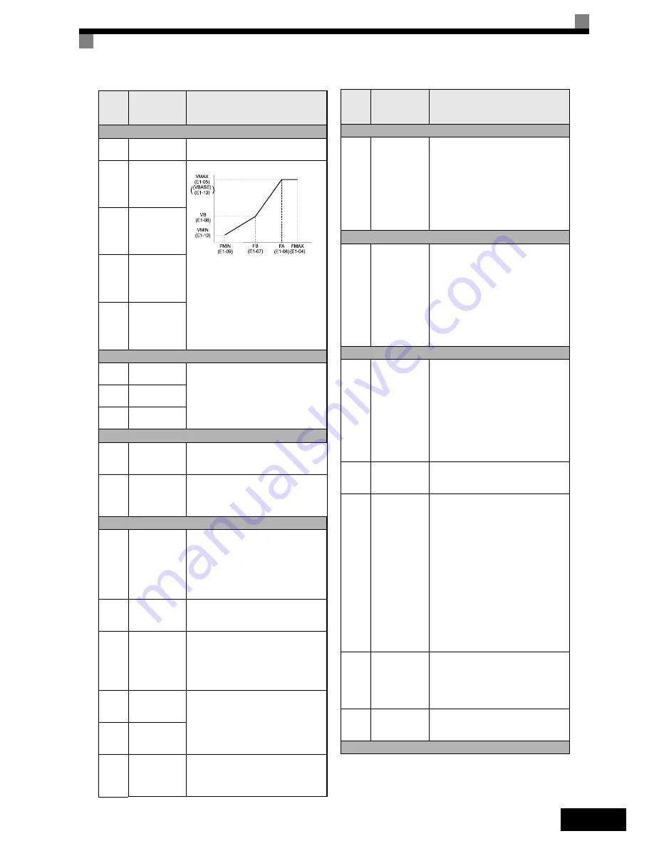
E1-04

Max. output 
frequency 
(FMAX)

To set V/f characteristics in a straight 
line, set the same values for E1-07 
and E1-09. In this case, the setting for 
E1-08 will be disregarded.
Always ensure that the four frequen-
cies are set in the following order:
E1-04 (FMAX) 

 E1-06 (FA) > E1-07 

(FB) 

 E1-09 (FMIN)

E1-05

Max. output 
voltage 
(VMAX)

E1-06

Base fre-
quency (FA)

E1-13

Base Voltage
(VBASE)

Motor Data Settings

E2-01

Motor rated 
current

Sets the motor data. Set the correct 
values if the thermal motor protection 
is used. 

E2-03

Motor no-load 
current

E2-05

Motor line-to-
line resistance

Digital I/O Settings

H1-01 

to 

H1-05

Terminal S3 to 
S7 function 
selection

Refer to 

page 20, Digital Input Func-

tion Selections (H1-01 to H1-05)

 for a 

list of selections

H2-01 

and

H2-02

Terminal M1-
M2 and M3-
M4 function 
selection

Refer to 

page 20, Digital Output Func-

tion Selections

 for a list of selections

Analog I/O Settings

H3-08

Analog input 
A2 signal level 
selection

Selects the signal level input at multi-
function analog input A2.
0:0 to +10V (11 bit).

2:4 to 20 mA (9-bit input).

3:0 to 20 mA (9-bit input)
Ensure to switch S1-2 to “V” before 
using a voltage input. 

H3-09

Analog input 
A2 function 
selection.

Selects the multi-function analog 
input function for terminal A2. 

H3-13

Terminal A1/
A2 switching

Selects on which terminal the main 
frequency reference can be input.
0:Use analog input 1 on terminal A1 

for main frequency reference.

1:Use analog input 2 on terminal 

A2 for main frequency reference.

H4-01

Terminal FM 
monitor selec-
tion

Sets the number of the monitor item 
to be output (U1-

††

) at terminal FM/

AM.

H4-04

Terminal AM 
monitor selec-
tion

H4-05

Terminal AM 
gain

Sets the analog output AM gain. 
Sets the percentage of the monitor 
value that is equal to 10V output at 
terminal AM. 

Param-

eter 

Num-

ber

Name

Description

Output Voltage (V)

Frequency (Hz)

Motor Protection

L1-01

Motor protec-
tion selection

0:Disabled
1:General-purpose motor protection 

(fan cooled motor)

2:Inverter motor protection (externally 

cooled motor)

3:Vector motor protection

When the Inverter power supply is 
turned off, the thermal value is 
reset, so even if it is enabled, pro-
tection may not be effective.

Power Loss Ride Through

L2-01

Momentary 
power loss 
detection

0:Disabled (DC bus undervoltage 

(UV1) detection)

1:Enabled (Restarted when the 

power returns within the time set 
in L2-02. When L2-02 is 
exceeded, DC bus undervoltage 
is detected.)

2:Enabled while CPU is operating. 

(Restarts when power returns dur-
ing control operations. Does not 
detect DC bus undervoltage.)

Stall Prevention

L3-01

Stall preven-
tion selection 
during accel

0:Disabled (Acceleration as set. With 

a heavy load, the motor may stall.)

1:Enabled (Acceleration stopped 

when L3-02 level is exceeded. 
Acceleration starts again when 
the current has fallen below the 
stall prevention level).

2:Intelligent acceleration mode (Using 

the L3-02 level as a basis, accelera-
tion is automatically adjusted. Set 
acceleration time is disregarded.)

L3-02

Stall preven-
tion level dur-
ing accel

Effective when L3-01 is set to 1 or 2.
Set as a percentage of Inverter rated 
current.

L3-04

Stall preven-
tion selection 
during decel

0:Disabled (Deceleration as set. If 

deceleration time is too short, a DC 
bus overvoltage may result.)

1:Enabled (Deceleration is stopped 

when the DC bus voltage 
exceeds the stall prevention 
level. Deceleration restarts when 
the voltage falls below the stall 
prevention level again.)

2:Intelligent deceleration mode 

(Deceleration rate is automatically 
adjusted so that the Inverter can 
decelerate in the shortest possible 
time. The set deceleration time is 
disregarded.)

When a braking option (Braking Unit) 
is used, always set to 0.

L3-05

Stall preven-
tion selection 
during running

0:Disabled (Runs as set. With a 

heavy load, the motor may stall.)

1:Deceleration using deceleration 

time 1 (C1-02.)

2:Deceleration using deceleration 

time 2 (C1-04.)

L3-06

Stall preven-
tion level dur-
ing running

Effective when L3-05 is 1 or 2.
Set as a percentage of the Inverter 
rated current.

Fault Restart

Param-

eter 

Num-

ber

Name

Description

Summary of Contents for CIMR-E7Z -

Page 1: ...own Model CIMR E7Z 200V Class Single phase 0 4 to 110 kW 400V Class 3 phase 0 4 to 300 kW Quick START GUIDE Manual No I64E EN 01 VARISPEED E7 Quick Start Guide Manual No I64E EN 01 English Deutsch Esp...

Page 2: ...Wiring Main Circuit Inputs EN 11 Keypad Operation EN 13 Digital Operator Display optional EN 13 Power Up and Basic Parameter Setup EN 15 Start Up Procedure EN 15 Before Power Up EN 16 Display after Po...

Page 3: ...eneral LC RC interference suppression filters capacitors or overvoltage protection devices to the inverter input or output To avoid unnecessary overcurrent faults etc being displayed the signaling con...

Page 4: ...ther unauthorized persons must not be allowed access to these inverters Keep these Safety Precautions and Instructions for Use readily accessible and supply them to all persons with any form of access...

Page 5: ...y inverters design and install electrical switch gear It also describes the measures necessary to comply with the EMC Directive The manual s installation and wiring instructions must therefore be foll...

Page 6: ...s so as to maximize the area of the end of the lead in contact with the ground terminal e g metal plate Shielded Cable Use a cable with braided shield Ground the maximum possible area of the shield It...

Page 7: ...d from floating dust When installing or operating the Inverter always take special care so that metal powder oil water or other foreign matter does enter the Inverter Do not install the Inverter on co...

Page 8: ...required horizontally and vertically for IP00 IP20 and NEMA 1 Inverters 2 Always remove the top protection cover after installing an Inverter with an output of 18 5 kW or less in a panel Always provid...

Page 9: ...0 to 10 V 3 2 k 2 1 V 2 k Reverse Run Stop External fault Fault reset Multi step speed setting 1 Multi step speed setting 2 Jog frequency selection Multi function digital inputs Factory settings Anal...

Page 10: ...gnal Name Function Signal Level Digital input signals S1 Forward run stop command Forward run when ON stopped when OFF 24 VDC 8 mA Photocoupler isolation S2 Reverse run stop command Reverse run when O...

Page 11: ...tions output Differential input PHC isolation S IG Signal common 1 The default settings are given for terminals S3 to S7 For a 3 wire sequence the default settings are a 3 wire sequence for S5 multi s...

Page 12: ...on PNP by using the jumper CN5 An external power supply is also supported providing more freedom in signal input methods Table 3 Sinking Sourcing Mode and Input Signals Internal Power Source Sinking M...

Page 13: ...300A 9000 2055 215 240 350 4000 55000 A50P350 4 500V 350A 12000 2075 283 240 450 7100 64000 A50P450 4 500V 450A 20000 2090 346 240 550 11000 64000 A50P600 4 500V 600A 36000 2110 415 240 600 13000 830...

Page 14: ...contactor MC between the Inverter and motor is not turned ON or OFF during inverter operation If the MC is turned ON during the Inverter is operation a large inrush current will be created and the in...

Page 15: ...ey Selects user parameter numbers and decrements parameter set tings Used to move to the previous item or data DATA ENTER Key Enters menus and parameters and validates parameter settings RUN Key Start...

Page 16: ...ower ON Confirm Status Basic settings Quick Programming Mode Set E1 03 V f default 400V 50Hz Motor cable over 50 m or heavy load possibly causing motor to stall or overload Non rotating autotuning for...

Page 17: ...Autotuning can be used to improve the performance when very long motor cables are used or when motor and inverter have different power ratings To perform autotuning set T1 02 Motor rated power and T1...

Page 18: ...lculation 1 Enabled speed calculation 2 Disabled current detection 3 Enabled current detection b3 14 Bi directional speed search selection Disables or enables the bi directional capabilities of the sp...

Page 19: ...or protec tion selection 0 Disabled 1 General purpose motor protection fan cooled motor 2 Inverter motor protection externally cooled motor 3 Vector motor protection When the Inverter power supply is...

Page 20: ...0 Input terminal status Shows input ON OFF status Param eter Num ber Name Description 1 FWD command S1 is ON 1 REV command S2 is ON 1 Multi input 1 S3 is ON 1 Multi input 2 S4 is ON 1 Multi input 3 S5...

Page 21: ...inal is not used 14 Fault reset Reset when turned ON 19 PI control disable 20 to 2F External fault Input mode NO contact NC contact Detection mode Normal during operation Digital Output Function Selec...

Page 22: ...motor Check external sequence logic so that only one input is activated at a time External fault input from Communications Option Card Check for an external fault condition Verify the parameters Verif...

Page 23: ...rrent matches the motor rated current only in stop condi tio The DC bus voltage has exceeded the overvolt age detection level Default detection levels are 200 V class 410 VDC 400 V class 820 VDC Incre...

Page 24: ...parameter b1 02 are set to 3 option board but no option board is installed Verify that the board is installed Remove the power supply and re install the option board again Recheck the setting of b1 01...

Reviews: