background image

7. Connection Procedure 

Mount the EtherCAT 
Communications Unit to the 
Inverter. 
 
*For details on how to mount the 

EtherCAT Communications 
Unit, 2-4 Mounting and Wiring 
for the EtherCAT 
Communication Unit in the 
Inverter MX2/RX Series 
EtherCAT Communications Unit 
User's Manual (Cat.No. I574). 

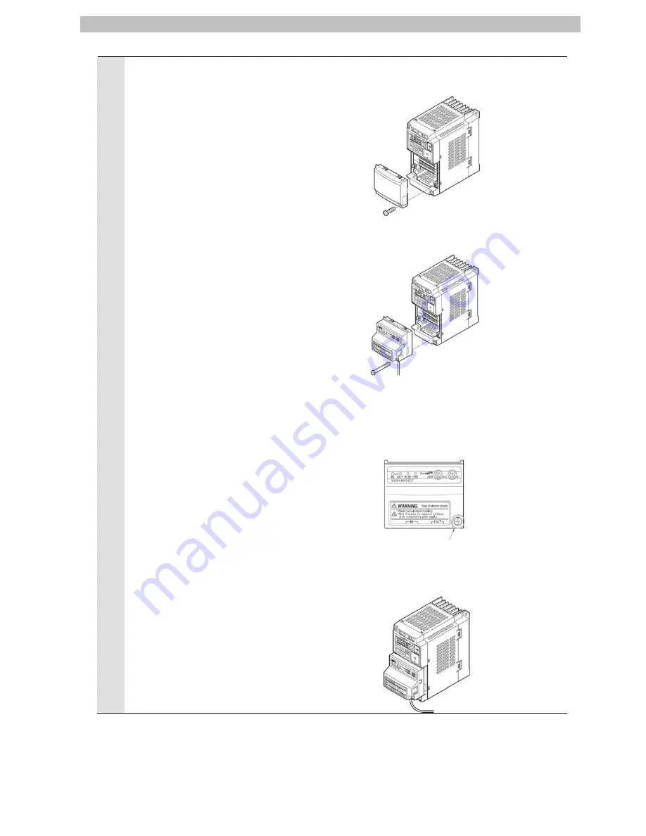
Removing the optional board cover from the Inverter front panel 

1. Loosen the mounting screw (x 1) from the optional board cover of the 

Inverter front panel. 

2. Remove the optional board cover. 


Mounting the EtherCAT Communication Unit onto the Inverter 

1. Mount the EtherCAT Communication Unit onto the location where the 

Inverter optional board cover that you removed was attached. Check 
that the connector is firmly connected. 


(Notes) When the EtherCAT Communication Unit is mounted, the main 

circuit and control circuit terminals of the Inverter are hidden. For 
this reason, be sure to wire the main circuit and control circuit 
terminals before mounting the EtherCAT Communication Unit. 

 
2. Tighten the mounting screw of the EtherCAT Communication Unit. 

Tighten the bottom right screw of the EtherCAT Communication Unit 

with the specified torque 

(46 N•cm, 4.7 kgf•cm). 


Connecting the ground cable of the EtherCAT Communication Unit 

1. Ground the FG cable of the EtherCAT Communication Unit. 

Cut the ground wire of the unit's FG cable to an appropriate length and 
ground it to the closest possible ground location. Also refer to the 
Inverter manual. 


 10

Summary of Contents for 3G3MX2 Series

Page 1: ...Machine Automation Controller NJ series EtherCAT Connection Guide OMRON Corporation 3G3MX2 Series Inverter P521 E1 01...

Page 2: ...ices 5 5 2 Device Configuration 6 6 EtherCAT Settings 7 6 1 EtherCAT Communications Settings 7 6 2 Allocating the Global Variables 7 7 Connection Procedure 8 7 1 Work Flow 8 7 2 Setting Up the Inverte...

Page 3: ...n for Correct Use of manuals for each device which is used in the system Cat No Model Manual name W500 NJ501 NJ series CPU Unit Hardware User s Manual W501 NJ501 NJ series CPU Unit Software User s Man...

Page 4: ...s SDO Communications Communications using Service Data objects This method is used to read and write the specified slave unit data from the master unit when required The EtherCAT port built into the N...

Page 5: ...conform to 4 It is prohibited to copy to reproduce and to distribute a part of or whole part of this document without the permission of OMRON Corporation 5 This document provides the latest informati...

Page 6: ...to do and what not to do to ensure using the product safely Precautions for Correct Use Indicates precautions on what to do and what not to do to ensure proper operation and performance Additional Inf...

Page 7: ...Name Model Version OMRON NJ series CPU Unit NJ501 OMRON Inverter 3G3MX2 A 1 1 or later OMRON EtherCAT Communications Unit 3G3AX MX2 ECT Additional Information As applicable devices above the devices l...

Page 8: ...ns for Correct Use The connection line of EtherCAT communication cannot be shared with other network such as Ethernet or EtherNet IP The switching hub for Ethernet cannot be used for EtherCAT Please u...

Page 9: ...ariables is shown below Output area Controller Destination device Destination device data Global variable name Data type Operation command to Inverter E001_Command WORD Output frequency E001_Frequency...

Page 10: ...e Inverter parameters 7 3 Setting Up the Controller Set up the Controller 7 3 1 Starting the Sysmac Studio and Setting the EtherCAT network configuration Start the Automation Software Sysmac Studio an...

Page 11: ...dure 7 2 Setting Up the Inverter Set up the Inverter 7 2 1 Hardware Setting Check the hardware switches on the Inverter Precautions for Correct Use Make sure that the power supply is OFF when you perf...

Page 12: ...er optional board cover that you removed was attached Check that the connector is firmly connected Notes When the EtherCAT Communication Unit is mounted the main circuit and control circuit terminals...

Page 13: ...e and check the hardware switches on the EtherCAT Communications Unit 3 Set the node address setting switches to 01 Set the node address to 1 4 Connect the communications cable to Communications conne...

Page 14: ...return from the tripping Mode key Parameter is displayed Move to the beginning of the next function group Data is displayed Cancel the setting and return to the parameter display Individual input mode...

Page 15: ...default value 00 00 a001 a002 04 a001 a002 02 a004 a002 Press the Increment Key two times Press the Enter Key Press the Increment Key once A002 parameter is displayed The parameter is displayed again...

Page 16: ...splayed when the factory default setting 04 Basic display is used a002 b001 b037 04 01 b037 The parameter is displayed Press the Increment Key three times Press the Enter Key Press the Increment Key f...

Page 17: ...he parameter is displayed Press the Mode Key once C001 parameter is displayed Press the Increment Key to move to C102 C102 parameter is displayed Press the Enter Key The initial data is displayed Pres...

Page 18: ...e Sysmac Studio Click the New Project Button 16 2 The Project Properties Dialog Box is displayed Click the Create Button In this document New Project is set as the project name 3 The New Project Pane...

Page 19: ...the Direct connection via USB Option in the Connection Type Field Click the OK Button 17 6 Select Online from the Controller Menu A confirmation dialog is displayed Click the Yes Button A displayed d...

Page 20: ...ouble click EtherCAT under Configurations and Setup in the Multiview Explorer Or right click EtherCAT under Configurations and Setup and select Edit 11 The EtherCAT Tab Page is displayed in the Edit P...

Page 21: ...of the comparison result Click the Apply actual network configuration Button 19 14 A confirmation dialog box is displayed Click the Apply Button Check that node address 1 and E001 3G3AX MX2 ECT Rev 1...

Page 22: ...e EtherCAT Slave Unit 1 Select Offline from the Controller Menu 2 Double click I O Map under Configurations and Setup on the Multiview Explorer or right click it and select Edit 3 The I O Map Tab Page...

Page 23: ...ames are created automatically from a combination of the device names and the I O port names For slave units the default device names start with an E followed by a sequential number starting from 001...

Page 24: ...from the Controller Menu 2 When an online connection is established a yellow bar is displayed on the top of the Edit Pane 3 Select Synchronization from the Controller Menu 4 The Synchronization Dialo...

Page 25: ...6 Check that the synchronized data is displayed with the color specified by Synchronized and that a message is displayed stating The synchronization process successfully finished If there is no proble...

Page 26: ...ormed normally 1 Select Mode RUN Mode from the Controller Menu 2 A confirmation dialog is displayed Click the Yes Button Check that the controller status on the Toolbox was changed to the RUN mode 3 C...

Page 27: ...L A IN Green Flickering In operation after establishing link OFF Link not established in physical layer ON Link established in physical layer L A OUT Green Flickering In operation after establishing...

Page 28: ...n make sure to complete all the steps and to place the operation in the safe state Check the Monitor Button and Stop Monitoring Button on the toolbar of the Sysmac Studio to see if the Controller is i...

Page 29: ...ocal Operations from EtherCAT are disabled 1 Remote Operations from EtherCAT are enabled Status Status Bit Name Meaning 0 Forward operation in progress 0 Stopped during reverse operation 1 During forw...

Page 30: ...12 Frequency matching 0 During acceleration deceleration 1 Frequency matching Status Bit Name Meaning 0 Forward operation in progress 0 Stopped during reverse operation 1 During forward operation 1 R...

Page 31: ...he 7 segment LED indicator Output frequency is 1 00 13 Enter 0 in the Output frequency E001_Frequency_reference and 0 in Operation command to Inverter E001_Command 14 Check that the 7 segment LED disp...

Page 32: ...e factory default setting some settings may not be applicable as described in this procedure 8 1 Controller To initialize the settings of the Controller select Clear All Memory from the Controller Men...

Page 33: ...9 Revision History 31 9 Revision History Revision code Date of revision Revision reason and revision page 01 Mar 26 2013 First edition...

Page 34: ...2013 0911 P521 E1 01...

Reviews: