Page 11
Page 12
WARNING REGARDING EARTHING GROUND:
o
o
o
o
This equipment shall be connected to the DC supply
system earthing electrode conductor or to a bonding
jumper from an earthing terminal bar or bus to which the
DC supply system earthing electrode is connected.
This equipment shall be located in the same immediate
area (such as adjacent cabinets) as any other equipment
that has a connection between the earthed conductor of
the same DC supply circuit and the earthing conductor,
and also the point of earthing of the DC system. The DC
system shall not be earthed elsewhere.
The DC supply source is to be located within the same
premises as this equipment.
There shall be no switching or disconnecting devices in
the earthed circuit conductor between the DC source and
the earthing electrode conductor.
Locate the DC circuit breaker of the external power source, and switch the circuit
breaker to the OFF position.
Prepare a power cable using a three conductor insulated wire (not supplied) with
12AWG to 14AWG thickness. Cut the power cable to the length required.
Strip approximately 3/8 of an inch of insulation from the power cable wires.
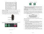
Connect the ground wire to the grounding screws on the back of the module.
Ground Screw Location
Connect the power cables to the module by fastening the stripped ends to the DC
power connector.
Power Connections
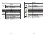
Power Options
WARNING: The positive lead of the power source must be connected to the
“+” terminal on the module and the negative lead of the power source to the
“-“ terminal on the module as shown above.
WARNING: Note the wire colors used in making the positive, negative and
ground connections. Use the same color assignment for the connection at
the circuit breaker.
Connect the power wires to the circuit breaker and switch the circuit breaker ON.
If any modules are installed, the Power LED(s) will indicate the presence of power.
During the installation, ensure that the ground potentials are maintained throughout
the system connections. This includes but not limited to the power source ground
and any shielded cabling grounds.
NEVER ATTEMPT TO OPEN THE CHASSIS OR
SERVICE THE POWER SUPPLY. OPENING THE
CHASSIS MAY CAUSE SERIOUS INJURY OR DEATH.
THERE ARE NO USER REPLACEABLE OR
SERVICEABLE PARTS IN THIS UNIT.
WARNING!!!
Make sure to disconnect both power connectors and the ground cables before
removing the equipment.
4) Connect Cables
a. Insert the SFP/SFP+ transceiver into the SFP receptacle on the front of
the module (see the SFP Data Sheet 091-17000-001 for supported Gigabit
transceivers or 091-17400-001 for supported 10G transceivers).
NOTE: The release latch of the SFP fiber transceiver must be in the closed
(up) position before insertion.
b. Connect an appropriate multimode or single-mode fiber cable to the fiber port
on the front of the module. It is important to ensure that the transmit (TX) is
attached to the receive side of the transceiver at the other end and the receive
(RX) is attached to the transmit side. When using single-fiber (SF) models, the
TX wavelength must match the RX wavelength at the other end and the RX
wavelength must match the TX wavelength at the other end.
c. Connect the Ethernet 10/100/1000 RJ-45 port using a Category 5 or better
cable to an external 10BASE-T, 100BASE-TX or 1000BASE-T Ethernet device.

