Page 5
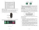
Front Panel Layout
Serial Console Port
To configure the module using the serial port, attach a DB-9 serial (RS-232)
equipped computer with terminal emulation software such as Procomm or Putty
to the serial port on the module using a RJ-45 to DB-9 serial cable (not included).
Some computers do not come with DB-9 serial port connectors and may require a
USB-to-serial port adapter.
The port is a standard RS-232 asynchronous serial interface. The serial ports is
configured for 57,600bps, 1 stop, 8 data, parity none. The serial adapter cable
pin-outs are illustrated below.
Standard RJ-45 to DB-9 serial cable pin-out
Reset Button
A Reset Button is available on the front of the switch to restore the switch to factory
default values. Press and hold the reset button for more than 5 seconds to restore
the switch to factory default values.
Installation Procedure
1) Configure DIP-switches
2) Installing the Module
3) Apply DC Power
4) Connect Cables
5) Verify Operation
Page 6
1) Configure DIP-switches
DIP-switches are located on the top of the module. The DIP-switches are used to
configure modes of operation and networking features.
DIP-switch Bank Locations
The table below provides a description of each DIP-switch position and function.
Switch
Position
Legend
Function
SW1
LEFT
Single Switch
Mode of Operation
RIGHT
Dual Switch
SW2
LEFT
Switch
RIGHT
Directed Switch
SW3
LEFT
Off
Uplink Redundancy
RIGHT
Link Protection
SW4
LEFT
No Return
RIGHT
F1 Return
SW5
LEFT
MAC Learning
MAC Learning Enabled (factory default)
RIGHT
Off
MAC Learning Disabled
SW6
LEFT
Off
Pause Disabled (factory default)
RIGHT
Pause
Pause Enabled
SW7
LEFT
L2CP Tunnel
L2CP Tunnel (factory default)
RIGHT
Discard
L2CP Tunnel Discard
SW8
LEFT
OPT1 Off
Reserved
RIGHT
On
DIP-switch Definitions
SW1 and SW2: Mode of Operation
The module supports Switch, Directed Switch and Dual Device modes.
The modes are described with MAC learning enabled. When MAC learning is
disabled, unicast packets are forwarded to all ports.

