Environmental Notices
The equipment covered by this manual must be disposed of or recycled in
accordance with the Waste Electrical and Electronic Equipment Directive (WEEE
Directive) of the European Community directive 2012/19/EU on waste electrical and
electronic equipment (WEEE) which, together with the RoHS Directive 2015/863/
EU, for electrical and electronic equipment sold in the EU after July 2019. Such
disposal must follow national legislation for IT and Telecommunication equipment
in accordance with the WEEE directive: (a) Do not dispose waste equipment with
unsorted municipal and household waste. (b) Collect equipment waste separately.
(c) Return equipment using collection method agreed with Omnitron.
The equipment is marked with the WEEE symbol shown to indicate that it
must be collected separately from other types of waste. In case of small items the
symbol may be printed only on the packaging or in the user manual. If you have
questions regarding the correct disposal of equipment go to www.omniton-systems.
com/support or e-mail to Omnitron at [email protected].
Safety Warnings and Cautions
ATTENTION: Observe precautions for handling electrostatic discharge
sensitive devices.
WARNING: Potential damage to equipment and personal injury.
WARNING: Risk of electrical shock.
WARNING: Hot surface.
RuggedNet
10G/Mi
Quick Start Guide
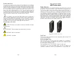
Product Overview
The RuggedNet 10G/Mi is a ruggedized unmanaged industrial Ethernet switch that
features two 1/10G uplink ports and four or eight 10/100/1000 RJ-45 copper user ports.
The mode of operation can be configured using easily accessible DIP-switches or
using Web, Telnet, SSH, SNMPv1/v2c/v3 or Serial Console management interfaces.
These management interfaces provide access to filtering and security options, such
as, broadcast storm prevention, IGMP, IEEE 802.1x, RADIUS, and Access
Control Lists. Email event notification and alarm reporting is provided using Simple
Mail Transfer Protocol. To access the user manuals for the Web Interface (3xxxUM-02x
Web Interface OmniConverter RuggedNet Switches) and Command Line Interface
(3xxxUM-01x Command Line Interface OmniConverter RuggedNet Switches),
access the product pages at: www.omnitron-systems.com.
RuggedNet 10G/Mi 6 and 10 Port
Front Panel
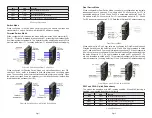
The front of the module provides access to the management (serial console), RJ-45
user ports and uplink ports.
RJ-45 and Uplinks Ports
The RJ-45 Ethernet user port supports 10BASE-T, 100BASE-TX and 1000BASE-T
protocols, auto-negotiation, auto MDI/MDI-X crossover and can be manually forced
to a specific speed and duplex mode.
The module supports two 1/10G SFP/SFP+ transceiver uplink ports.
The SFP/SFP+ ports support SERDES copper and fiber 10GBASE-X and
1000BASE-X transceivers, and SGMII 10/100/1000BASE-T copper transceivers.
Page 3
Page 4

