User Manual V1.1
User Manual
-Installation -Operation
Omniksol-1k/1.5k-TL2-M Omniksol-2k/2.5k/3k-TL3-S Omniksol-3k/3.68k/4k-TL3 Omniksol-5k/6k-TL3
Omnik New Energy Co., Ltd.
Page 1: ...User Manual V1 1 User Manual Installation Operation Omniksol 1k 1 5k TL2 M Omniksol 2k 2 5k 3k TL3 S Omniksol 3k 3 68k 4k TL3 Omniksol 5k 6k TL3 Omnik New Energy Co Ltd...
Page 2: ......
Page 3: ...hecklist 17 4 1 Assembly parts 17 4 2 Product Appearance 18 4 3 Product Identification 19 4 4 Further Information 20 5 Installation 21 5 1 Safety 21 5 2 Mounting Instructions 22 5 3 Safety Clearance 2...
Page 4: ...card 46 8 3 Register on monitoring website 49 8 4 Login monitoring System 52 8 5 WiFi card 57 8 6 Netwoek Settings 58 8 7 Ethernet Card 67 8 8 Installation of Ethernet card 68 8 9 RS485 card 70 9 Recy...
Page 5: ...Omniksol 3k 3 68k 4k TL3 Omniksol 5k 6k TL3 Please keep this user manual all time available in case of emergency 1 2 Symbols Used CAUTION CAUTION indicates a hazardous condition which if not avoided...
Page 6: ...tended to install Or uninstall the Omnik Grid Tie Solar Inverter NOTICE Hereby qualified personnel means he she has the valid license from the local authority in Installing electrical equipment and PV...
Page 7: ...mation of authorized repair facility for any maintenance or repairmen Any unauthorized actions including modification of product functionality of any form will affect the validation of warranty servic...
Page 8: ...rface The components inside the inverter will release a log of heat during operation DO NOT touch aluminum housing during operating An error has occurred Please go to Chapter 10 Trouble Shooting to re...
Page 9: ...e basic requirements of the Guideline Governing Low Voltage and Electromagnetic Compatibility No unauthorized perforations or modifications Any unauthorized perforations or modifications are strictly...
Page 10: ...s more PV panels connected Wide MPP voltage range ensure high yield under various weather conditions High MPP tracking accuracy ensure the minimum power loses during converting Complete set of protect...
Page 11: ...er of MPP trackers 1 1 Number of DC Connection 1 1 DC Connection Type Amphenol Connector Amphenol Connector Output AC Max AC Appaeent Power VA 1000 1500 Nominal AC Power W 1000 1500 Nominal Grid Volta...
Page 12: ...1000 6 1 EN61000 6 3 EN 61000 6 2 EN61000 6 4 EN61000 3 2 EN 61000 3 3 Grid Standard VDE AR N 4105 VDE 0126 1 1 C10 11 G83 2 UTE C 15 721 1 CEI 0 21 EN50438 NB T32004 IEC62116 IEC61727 IEC61683 IEC600...
Page 13: ...r of DC Connection 1 1 1 DC Connection Type Amphenol Connector Amphenol Connector Amphenol Connector Output AC Max AC Appaeent Power VA 2200 2750 3300 Nominal AC Power W 2000 2500 3000 Nominal Grid Vo...
Page 14: ...1000 6 1 EN61000 6 3 EN 61000 6 2 EN61000 6 4 EN61000 3 2 EN 61000 3 3 Grid Standard VDE AR N 4105 VDE 0126 1 1 C10 11 G83 2 UTE C 15 721 1 CEI 0 21 EN50438 NB T32004 IEC62116 IEC61727 IEC61683 IEC600...
Page 15: ...B 1 A 1 B 1 A 1 B 1 Number of DC Connection A 1 B 1 A 1 B 1 A 1 B 1 DC Connection Type Amphenol Connector Amphenol Connector Amphenol Connector Output AC Max AC Appaeent Power VA 3300 3680 4400 Nomin...
Page 16: ...dard EN 61000 6 1 EN61000 6 3 EN 61000 6 2 EN61000 6 4 EN61000 3 11 EN 61000 3 12 Grid Standard VDE AR N 4105 VDE 0126 1 1 C10 11 G59 3 EN50438 NB T32004 IEC62116 IEC61727 IEC61683 IEC60068 Physical S...
Page 17: ...ber of MPP trackers A 1 B 1 A 1 B 1 Number of DC Connection A 1 B 1 A 1 B 1 DC Connection Type Amphenol Connector Amphenol Connector Output AC Max AC Appaeent Power VA 5500 6600 Nominal AC Power W 500...
Page 18: ...EN 62109 1 IEC EN 62109 2 EMC Standard EN 61000 6 1 EN61000 6 3 EN 61000 6 2 EN61000 6 4 EN61000 3 11 EN 61000 3 12 Grid Standard G59 3 CEI 0 21 NB T32004 Physical Structure Dimensions WxHxD mm 343 4...
Page 19: ...side completeness for any visible external damage on the inverter or any accessories Contact your dealer if anything is damaged or missing A B C D E F G H Object Quantity Description A 1 Omnik inverte...
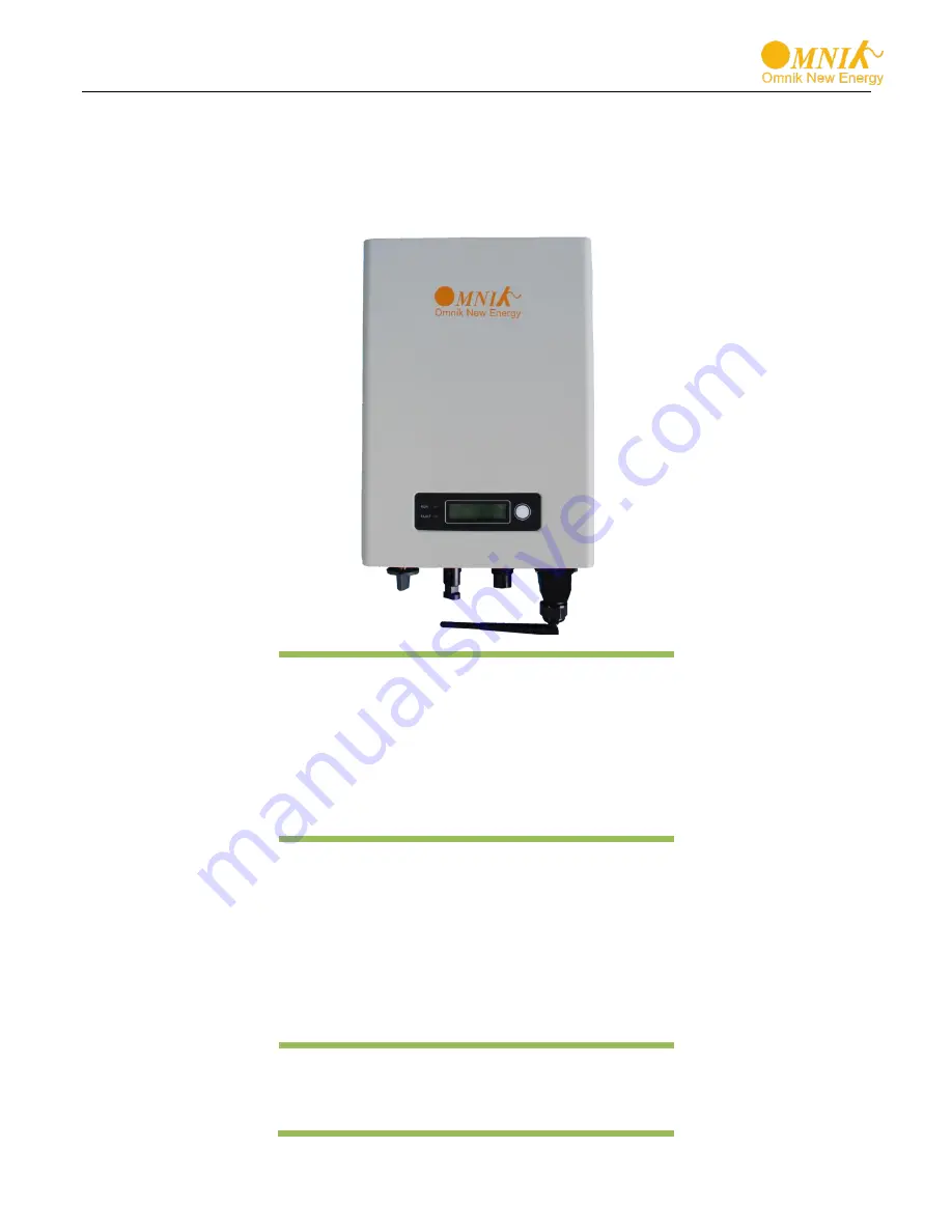
Page 20: ...LED light Green RUN B LED light Red FAULT C Function key for displays and choice of language Bottom style 1 Object Description A DC switch B Plug connectors for DC input C Terminal for grid connection...
Page 21: ...ormation such as type of the inverter and inverter specifications are specified on the side name plate The name plate is on the middle part of the right side of the inverter housing And the following...
Page 22: ...20 4 4 Further Information If you have any further questions concerning the type of accessories or installation please check our website www omnik solar com or contact our service hotline...
Page 23: ...r Do not expose to rain and snow cover to enhance inverter life time The installation site MUST have good ventilation condition DANGER DANGER to life due to potential fire or electricity shock DO NOT...
Page 24: ...vel Make sure the wall you selected is strong enough to handle the screws and bear the weight of the inverter Ensure the device is properly fixed to the wall It is not recommended that the inverter is...
Page 25: ...e following minimum clearances to walls other devices or objects to guarantee sufficient heat dissipation and enough space for pulling the electronic solar switch handle Direction Minimum clearance Ab...
Page 26: ...5 4 2 First according to the marks drill 2 holes in the wall Then place 2 expansion tubes in the holes using a rubber hammer Next make 2 screws through the mounting holes in the bracket then tighten t...
Page 27: ...oles on the wall according to the wall mounting bracket in the carton box Application to models Omniksol 2k 2 5k 3k TL3 S Omniksol 3k 3 68k 4k TL3 and Omniksol 5k 6k TL3 Omniksol 2k 2 5k 3k TL3 S Omni...
Page 28: ...bber hammer Next make 4 screws through the mounting holes in the bracket then tighten the screws into the expansion tubes So far the wall mounting bracket is fixed already 5 4 6 Align both sides of th...
Page 29: ...rner of the inverter as the picture showed below Recommended padlock dimension A Shackle Diameter 5 7 mm B Vertical Clearance 8 15 mm C Horizontal Clearance 12 20 mm Stainless solid hanger and secured...
Page 30: ...ANGER to life due to potential fire or electricity shock NEVER connect or disconnect the connectors under load NOTICE Electrical connections shall be carried out in accordance with the applicable regu...
Page 31: ...Length of cable 4 mm2 6 mm2 Omniksol 2k TL3 S 10A 30m Omniksol 2 5k TL3 S 12 5A 24m Omniksol 3k TL3 S 15A 20m 30m Model Rated current Length of cable 4 mm2 6 mm2 Omniksol 3k TL3 13A 20m 30m NOTICE Use...
Page 32: ...14mm 0 55 of the inner wrapper then dress the conductor terminals with ferrules or tin soldering 2 Check that all parts of AC connector are present Then slide hex nut onto the cable and insert the ca...
Page 33: ...the locker according to the direction instructed by the marks on the locker 6 If you need to separate the connectors please use a screwdriver to press the lock tongue rotate the locker according to t...
Page 34: ...5k TL3 21 7A 18m 30m Omniksol 6k TL3 26A 15m 25m 1 Strip the cable 12mm 2 Insert the striped cable into cord end terminal and insert the assembly into barrel 3 Then the line will like the picture belo...
Page 35: ...he DC characteristics of the mare illustrated as the following table Inverter Type MPP Tracker Max DC Power Max DC Voltage Max DC Current Omniksol 1k TL2 M 1 1250W 500V 10A Omniksol 1 5k TL2 M 1750W 5...
Page 36: ...5k TL2 M 30m 48m Model Length of cable 2 5 mm2 4 mm2 Omniksol 2k TL3 S 40m 64m Omniksol 2 5k TL3 S 50m 80m Omniksol 3k TL3 S 60m 96m 6 3 2 For Omniksol 3k 3 68k 4k TL3 and Omniksol 5k 6k TL3 there ar...
Page 37: ...st be isolated from the power supply while being assembled or disassembled The end product must provide protection from electric shock The use of PVC cables is not recommended Unplugging under load PV...
Page 38: ...d voltage 1000V IEC CEI 600V UL Upper limiting temperature 105 C IEC CEI Safety class II Tools required ill 1 Crimping tool incl locator and built in crimping insert Type PV ES CZM 18100 PV ES CZM 191...
Page 39: ...ge ous to use tinned conductors It is unadvisable to use non tinned cables of type H07RN F since with oxidized copper wires the contact resistances of the crimp connection may exceed the permitted lim...
Page 40: ...the tools PV MS Or Screw on the cable gland with the tools PV WZ AD GWD and PV SSE AD4 In any case The tightening torque must be adapted to the solar cables used in each specific case Typical values...
Page 41: ...39 Refer to cable manufactures specification for minimum bending radius...
Page 42: ...check and set the data In addition the user can press the function key to illuminate the LCD screen NOTICE Omnik inverter is not an aligned measuring instrument for current voltage or power consumpti...
Page 43: ...kWh 3 PV Voltage V Vpv xxx x V 4 PV Current A Ipv xx x A 5 Grid voltage V Vac xxx x V 6 Grid current A Iac xx x A 7 Grid frequency Hz Frequency xx x Hz 8 Models Omniksol 3k TL3 S 9 Standard Italy 10...
Page 44: ...current Frequency The grid frequency Model The model of the inverter Standard Choose standard for different country reference to 7 3 for further information Version Long press to check the firmware ve...
Page 45: ...line of LCD displays Standard for example Italy c Hold the button for 5 seconds or more until the first line of LCD displays Set Change the standard by pressing the Function button one at a time d Whe...
Page 46: ...y Fault F05 Bus Volt Low F06 Bus Volt High F09 No Utility F10 Ground Current Fault F11 Bus Unbalance F12 10min Over Volt F13 Over Temp Fault F15 PV Volt High F17 Grid Volt Fault F18 Isolation Fault F1...
Page 47: ...cking the box please check the parts according to the below list Contact the manufacturer immediately when you find any damage missing or wrong model Omnik provide 2 kinds of GPRS cards One is a stand...
Page 48: ...2 Installation of GPRS WiFi card Warning Before installing the GPRS card to inverter you must turn off both the AC side and DC side of inverter to make sure personal safety No Name A 14 pin connector...
Page 49: ...river as shown in Picture above and keep the screws aside The standard connector has two holes Use the single hole rubber washer to take place of the double hole rubber washer Insert the GPRS antenna...
Page 50: ...hile using the second kind of GPRS card just insert the SIM card into the card slot Then insert the GPRS card into the inverter Install the communication box back to the inverter While the installatio...
Page 51: ...e http www omnikportal com click register to enter the user registration page follows the requirements for registration please fill in the information for register After successful registration enter...
Page 52: ...ase read the Omnik service agreement carefully the enclosure is the cost list for all the countries please choose your operators End User means the final user you must fill it Fill in the power statio...
Page 53: ...51 Fill in the power station information After the register you may enter next chapter 8 4 Login Monitoring System...
Page 54: ...nd account activation open the login interface as below Input the correct email and code Enter the PV monitoring system Then you can monitor and manage the power station Input the email and code User...
Page 55: ...53 List of power station Navigation Bar Not yet open Back to user interface Enter the sharing case Enter the configure company account interface Add one case under your account Reset password...
Page 56: ...54 Main interface of Power Station Change case Case info search Power station info Energy saving Real time power and generated energy switchover Print current figure...
Page 57: ...55 Real Time Interface History Interface Internal temperature Latest data collecting time Parameter options Choose the aim inverter...
Page 58: ...56 Alert Interface System Setting Interface...
Page 59: ...er had not installed the WiFi card please go to 8 2 Installation of GPRS WiFi card first then go to 8 6 Network Settings After unpacking the box please check the parts according to the below list Cont...
Page 60: ...g tablet PC and smart phone that enables WiFi 2 Obtain an IP address automatically Open Wireless Network Connection Properties double click Internet Protocol Version 4 TCP IPv4 Select Obtain an IP ad...
Page 61: ...twork connection and click View Wireless Networks Select wireless network of the data logging module no passwords required as default The network name consists of AP and the serial number of the produ...
Page 62: ...er and enter 10 10 100 254 the Default IP address of WiFi card you may set domain name access please see the picture 6 14 then fill in username admin and password admin both of which are admin as defa...
Page 63: ...61 b In the configuration interface of WiFi module you can view general information of the module Follow the setup wizard to start quick setting Click Wizard to start admin admin...
Page 64: ...62 Click Start to continue Click Refresh to search available wireless networks...
Page 65: ...Next Notice If the signal strength RSSI of the selected network is 10 which means unstable connection please adjust the antenna of the router or use a repeater to enhance the signal We recommend rout...
Page 66: ...password for the selected network then click Next Select Enable to obtain an IP address automatically then click Next Notice Turn off the firewall of the router Make sure the DHCP function of the rout...
Page 67: ...lick OK to restart If setting is complete the above page will display After your WiFi card set ok and get IP address from your router for example 192 168 16 8 You may see the IP address from inverter...
Page 68: ...66 You may also add your domain name of WiFi card to easy access according below picture after you set ok input http wifi you may also access the related page...
Page 69: ...d the Ethernet card please go to 8 3 Register on monitoring website If your inverter had not installed the WiFi card please go to 8 8 Installation of Ethernet card first After unpacking the box please...
Page 70: ...fore installing the Ethernet card to inverter you must turn off both the AC side and DC side of inverter to make sure personal safety Unscrew the four screws on the interface panel with the screwdrive...
Page 71: ...Wear the Ethernet cable into the waterproof terminals and waterproof terminals and the cover plate is installed Insert the Ethernet card into the inverter Connect the Ethernet cable to the Ethernet ca...
Page 72: ...the Ethernet cable to the router LAN port 8 9 RS485 card RS485 card is used for external communication device There are 3 connectors in the RS485 card The definition of the connectors is shown in the...
Page 73: ...NO Relay Normal Open 8 9 1 CON 1 CON 1 is used to communicate with Wi Fi Kit and GPRS Kit The connector of Kit is shown as below The definition of the connector is shown in the table More details can...
Page 74: ...t can be applied for solar projects of self consumption without power export to the grid It can ensure that the power generated by solar system will not export to grid at anytime There are 2 types of...
Page 75: ...73 The definition of the connector is shown in the table The second type of meter is used with CT as shown below No Meter CON 1 L Grid side 2 L Inverter side 3 N 4 N 5 6 7 A 8 B...
Page 76: ...e details can be obtained in the user manual of CHIT DIN Meter DDSU 666 CON 3 CON 3 is used to control the alarm LED It is a pair of Normally open contacts The load capacity of the Relay is 230 V 0 5...
Page 77: ...the end of its life must be collected separately and returned to an approved recycling facility Any device that you no longer required must be returned to your dealer or you must find an approved coll...
Page 78: ...heck 2 Re Flash software 3 Replace part or inverter F06 Bus Volt High 1 Test Value Wrongly 2 Software Issue 3 Hardware Broken 1 Restart to check 2 Re Flash software 3 Replace part or inverter F09 No U...
Page 79: ...ization F21 PV2 Over Current The input current of PV2 is over rated value May be there is something wrong with the hardware 1 Restart the inverter 2 If the problem persists please replace the inverter...
Page 80: ...ac Voltage at the AC side Vmpp Voltage at the Maximum Power Point Impp Amperage at Maximum Power Point AC Alternating Current Form of electricity supplied by Utility Company DC Direct Current Form of...
Page 81: ...ebsite nl omnik solar com Authorized Service Partner Omnik UK Service Center Address Office 7 2 London Bridge Walk London United Kingdom SE1 2SX Tel 44 0 20171531108 E mail Sales omniksolar co uk Webs...
Page 82: ...y retention User information Product Model Product ID Purchase Date Customer Name Historical Warranty Warranty date Troubleshooting Finished date Customer Signature Client retention User Information P...
Page 83: ...valid Warranty period is 5 years standard 10 years selectable effective after sealing During the warranty period if the product fails the quality of the original device or the production problem the c...