


EN
42
Electronic version
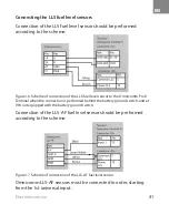
Connecting the contrllable auxiliary equipment
Connection of the contrllable auxiliary equipment should be
performed using the addition relay according to the scheme:
Figure 18. Scheme of connection of the Omnicomm LLS 20230 fuel level sensor to the
Omnicomm Profi Terminal if being connected ahead of the battery ground switch.
Figure 19. Scheme of connection of the controllable auxiliary equipment
Summary of Contents for Profi Wi-Fi 3.0
Page 2: ...RU 1 2 3 7 8 8 21 21 22 22...
Page 3: ...RU 2 Omnicomm Profi Omnicomm Online GPS GSM Omnicomm Online...
Page 7: ...RU 6 0 30 12 1 1 10 1 1 5 1 30 100 2...
Page 10: ...RU 9 1 2 SIM 3 4 Omnicomm Configurator 5 Omnicomm Profi Omnicomm Profi GPS GPS GPS...
Page 11: ...RU 10 GPS GPS Wi Fi SIM SIM PIN PIN SIM SIM SIM SIM SIM...
Page 14: ...RU 13 1 Omnicomm Profi 2 1 3 2 4...
Page 15: ...RU 14 5 6 7...
Page 16: ...RU 15 GSM 8 GSM 9...
Page 17: ...RU 16 RS 232 RS 485 10 11 11 RS 485 10 RS 232...
Page 18: ...RU 17 24 R R 500 1000 1 0 5 12 24 13...
Page 19: ...RU 18 N P N 14 N P N 15...
Page 20: ...RU 19 LLS Omnicomm LLS AF 1 15 16 Omnicomm LLS 17 Omnicomm LLS AF...
Page 21: ...RU 20 12 24 18 Omnicomm LLS 20230 20240 19...
Page 22: ...RU 21 Omnicomm Configurator 25 70 50 35 5 Omnicomm Profi 1 15150 2 15150 6...
Page 23: ...RU 22 Omnicomm Profi 127055 68 70 1 8 800 100 24 42 7 495 989 62 20 info omnicomm ru 1 1 3...
Page 24: ...RU 23 Omnicomm Profi 29 32 30 160 024 03066711 2018...


