background image

Getting Started

17

Emissions Testing Using the PC

OmiSmoke emissions testing can be undertaken by using a PC (using the 
OmiGas/OmiSmoke Techcenter software) or the handset.

OmiSmoke can be added to the PC based OmiGas/OmiTechcenter system at any 
time, simply by connecting the ‘combo’ cable (OM1500/10) between the OmiSmoke 
handset socket and the auxiliary serial interface socket on the rear of the OmiGas unit 
(OM4500/1).

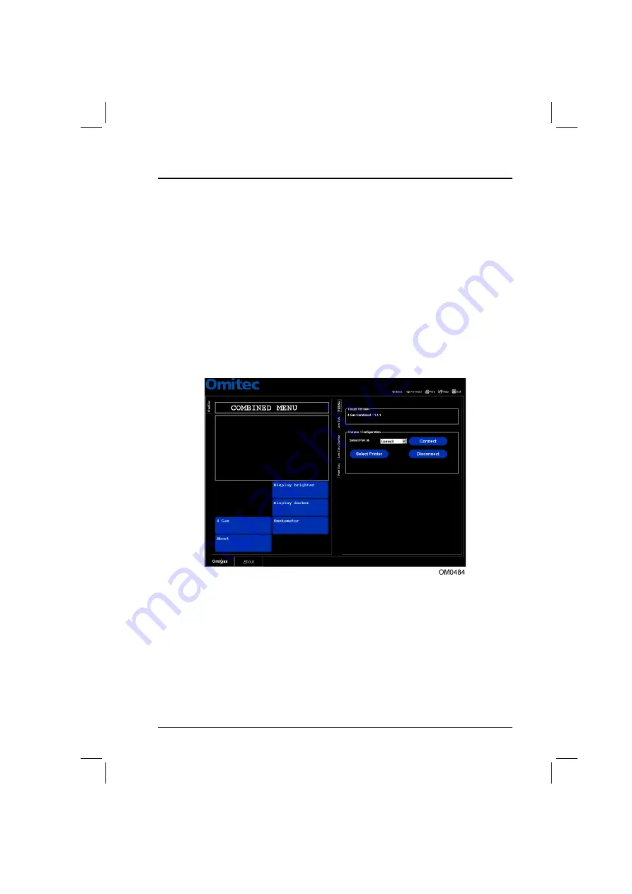
The PC system will need to recognise new hardware for the OmiSmoke. To achieve 
this, return to the main menu and select ‘ABORT’. The software will then re-establish 
communication and the message ‘Configuring Analyser - Please Wait’ will appear. 
This will then bring up the new ‘Combined Menu’, where the Smokemeter button will 
be added.

Navigation through the emissions test software using the PC, is assisted by the 
on-screen information and prompts which are displayed throughout the testing 
procedure. Each successive menu displayed on the PC will provide a number of 
options from which the technician may choose, using the ‘virtual’ buttons on the 
screen. Selecting an option is achieved by pointing to the relevant button with the 
mouse cursor and pressing the left hand mouse button to select. 

During a test procedure, the PC will display screens which inform the technician what 
the OmiSmoke analyser is currently doing. These screens do not provide options for 
the technician to select and are simply a commentary on the procedure. 

Summary of Contents for OmiSmoke

Page 1: ...Part Number I311592 English Issue 2 Omitec 2003 OmiSmoke Operating Instructions Part Number I311592 English Issue 2 Omitec 2003...

Page 2: ......

Page 3: ...15 Emissions Testing Using the Handset 16 Emissions Testing Using the PC 17 PC Navigation Short cut Buttons 18 Test Procedures Preparation of Vehicle Prior to Tests 19 Checks on Vehicle Before Tests 1...

Page 4: ...Readings 38 Smoke Raw Data 39 Printer Test 40 Clock Setup Mode 41 Calibration 42 Cleaning and Maintenance Cleaning 43 Cleaning the smokemeter 43 Cleaning the handset 43 Cleaning the linearity check f...

Page 5: ...l Vehicles MOT classes 4 and 7 Category B Public Service Vehicles Private Buses and Heavy Goods Vehicles MOT Class 5 and 6 OmiSmoke consists of two portable units the smokemeter which contains the mea...

Page 6: ...s from each test on the LCD Progress through the tests is indicated on the LCD while the 4 buttons allow for menu navigation and option selection 1 Test results printer 2 LCD 3 Up Navigation button 4...

Page 7: ...ectors located on the sides of the handset 1 Engine oil temperature sensor connector 2 Engine RPM sensor OmiSpeed BNC connector 3 9 pin D type VI Card reader input 1 Smokemeter 5 pin XLR connector 2 U...

Page 8: ...he measurement components of OmiSmoke 1 Receiver optics cover 2 Air intake 3 4 pin XLR power connector 4 5 pin XLR handset connector 5 Fuse 6 Power switch 7 Transmitter optics cover 8 Carry handle 9 E...

Page 9: ...smoke outlet 2 Exhaust sample probe input 3 Air knife vents Do not obstruct the air knife vents whilst running the OmiSmoke smokemeter Note The battery access cover is located on the underside of the...

Page 10: ...ollects gas samples from the test vehicle exhaust which are then analysed by OmiSmoke Take care to avoid contact with the exhaust system when inserting or removing the sample hose The exhaust system w...

Page 11: ...be into the exhaust following the quick guide below The probe should never be placed directly behind a bend in the exhaust pipe or close to the silencer or expansion box It should attach using the sec...

Page 12: ...cts to the OmiSmoke handset using the Oil Temperature Probe socket To monitor the engine temperature of the vehicle after it s warm up period prior to an emissions test the sensor probe must be insert...

Page 13: ...injury or come in contact with the probe or its cable resulting in damage to the probe and to the engine Take care not to come into contact with hot engine parts when inserting or removing the engine...

Page 14: ...he test and could cause burns Prolonged contact with engine oil may cause serious skin disorders including dermatitis and cancer of the skin Avoid unnecessary contact with engine oil and wash thorough...

Page 15: ...Follow the on screen instructions to complete the loading sequence then reboot when prompted Battery Charging The smokemeter is designed to run for intermittent operation on an internal 12V 200W batt...

Page 16: ...ll up and down through the menus press the Up and Down buttons until the required option is highlighted To select the highlighted option press the Tick button or to reject press the Cross button Each...

Page 17: ...Analyser Please Wait will appear This will then bring up the new Combined Menu where the Smokemeter button will be added Navigation through the emissions test software using the PC is assisted by the...

Page 18: ...elect to view the screen last displayed Select to return to the current screen if you have used the back button to view a previous screen Select to print the data for the current emissions test Select...

Page 19: ...are no obvious signs that the fuel injection pump governor has been tampered with e g seals are in place 7 The condition of the camshaft belt where visible 8 Raise engine to around 2500 rpm or half t...

Page 20: ...u The OmiSmoke will measure the Free Acceleration Smoke FAS output over the whole speed range of an engine no load from idle up to cut off speed where the engine is accelerated against its own inertia...

Page 21: ...icle types Public service vehicles Private bus Inc MOT class V and VI Heavy Goods Vehicle of which Reduced Pollution Certificate RPC testing is also available RPM Probe An RPM probe analyser can be us...

Page 22: ...ket VI Interface 9 pin D type On the Insert Smart Card screen press the tick key to confirm Data will then be read from the smart card to the OmiSmoke Press the cross key if a smart card is not used I...

Page 23: ...down button Fill the entire fieldbox to progress Press the tick key to enter a blank Spaces can be entered by also pressing the tick key The data will be confirmed Reading vehicle data Please wait Th...

Page 24: ...ES Follow the instructions given in section Engine Oil Temperature Sensor Probe paying particular attention to the use of the probe and the relevant warnings WARNING Incorrect use may result in damage...

Page 25: ...to purge the engine and effectively prepare for the test NOTE By selecting NO the test report will state No engine temperature taken The OmiSmoke will now check that the engine is at operating tempera...

Page 26: ...be into the exhaust following the quick guide below The probe should never be placed directly behind a bend in the exhaust pipe or close to the silencer or expansion box It should attach using the sec...

Page 27: ...the OmiSmoke with automatic calculation of pass fail status It may also request another repeated acceleration if insufficient data was recorded Fast Test Category A only After the 1st acceleration on...

Page 28: ...C A fail report after a category A test and an oil temperature of greater than 60 C but less than 80 C will not be produced and the user will be informed to raise the engine oil temperature to 80 C an...

Page 29: ...k the printer has paper and proceed Press the tick key and the display will show Printed Results Please Wait The print should take approximately 10 15 seconds A second set of results will be offered T...

Page 30: ...creen instructions On RPM Probe Check menu confirm you have a RPM probe OmiSpeed connected by pressing the tick key If you do not have a RPM probe press the cross key The OmiSmoke then goes through a...

Page 31: ...ents Connect RPM yes or no Tube warm up to 70 C Contamination bench reset and optic zero check Insert pipe into exhaust Smoke peak reading given Reset peak reading or Finish Remove pipe from exhaust S...

Page 32: ...ous Test from the main menu and follow the on screen instructions On RPM Probe Check menu confirm you have a RPM probe OmiSpeed connected by pressing the tick key If you do not have a RPM probe press...

Page 33: ...mmary of Events Connect RPM yes or no Tube warm up to 70 C Contamination bench reset and optic zero check Insert pipe into exhaust Smoke continuous reading given Finish remove pipe from exhaust Smoke...

Page 34: ...OmiSmoke will automatically calculate a new 7 5 default Once Linearity Test is selected from the main menu The OmiSmoke automatically performs a tube warm up procedure followed by a contamination che...

Page 35: ...lter is being used and is inserted correctly before trying again If repeat failure occurs check filter is clean See Cleaning and Maintenance section Once the linearity check is completed successfully...

Page 36: ...user check over the status of the equipment as part of routine maintenance or as part of Helpdesk diagnostics should a problem be encountered Smoke Head Info The Smoke Head Details screen displays the...

Page 37: ...er code Part List Rev Build parts list revision issue number Manufacturer Date Manufacturer Date Program Location Location of program S Ware Software number in smoke head S W rev Software revision iss...

Page 38: ...ser Notes Calculated K K value reading 0 00 unless filter inserted or fault Opacity Opacity within sample chamber of Smokemeter Accel Det Signal from acoustic sensor in smoke chamber typ 0 00 with no...

Page 39: ...temperature and battery voltage Reading Description User Notes Opacity 3 digit number typically 444 with no filter or fault Tube Temp 3 digit number typically 300 but can vary with tube temperature Ba...

Page 40: ...tab to enable the operator to check the printer for correct operation This is automatic on selection and will print out the following as means of checking the operation of the printer Smoke readings C...

Page 41: ...t time in the main window To change the time press the tick key The hour can be set by pressing the up or down arrow to display the correct hour then confirming by pressing the tick key The minutes ca...

Page 42: ...Test Procedures 42 Calibration The calibration menu is only available for use by authorised service calibration engineers...

Page 43: ...e handset The handset can be cleaned with a non aggressive cleaner and a soft cloth DO NOT immerse in water or use sprays of any kind Ensure that the handset is disconnected before carrying out any cl...

Page 44: ...Locate the LED mounted in the centre of the PCB facing the smoke chamber it is situated between 2 hexagonal mounts Note Be very careful not to knock this assembly as optical alignment is critical for...

Page 45: ...ge 3 Insert new paper roll 4 Feed a short length of paper through and close paper compartment lid Replacing the battery Rechargable batteries have a limited life and eventually need replacing If the s...

Page 46: ...s in EEPROM are invalid Contact Omitec Helpdesk Error 1002 Fan Control Returned Error State Fan control fault Contact Omitec Helpdesk Linearity check fail Use Correct Filter or Check Filter Failed LIN...

Page 47: ...pdesk Tube NOT warming up The tube temperature is not increasing when the heater is on Tube heater may be damaged Contact Omitec Helpdesk Contamination check Failed check hose or filter is not inserte...

Page 48: ...contact the smart card reader helpdesk Software error Report failure to meter manufacturer Smart card received incorrect message from smoke meter Contact Omitec Helpdesk Check details and that you are...

Page 49: ...mple Probe and Hose OM1500 9A Category B Sample Hose 2 5 m extension OM1500 9B Category B Sample Probe Only PB1106A Combo Cable Connection to OmiGas OM1500 10 DC Power Up Cable OM1500 14 Handset Cable...

Page 50: ...Omitec Instrumentation Ltd Hopton Industrial Estate London Road Devizes Wiltshire SN10 2EU United Kingdom Tel 44 0 1380 732000 Fax 44 0 1380 732001 email sales omitec com Web www omitec com...

Reviews: