background image

Section 2: Quick Start

2.1 Connection of sensors to the Datalog X-PRO

There are more than 60 different sensors that the user can connect to the

Datalog X-PRO.

One device can receive up to three different sensors

communicating with the main unit

through their sensor interfaces.

The sensors selected can be used to measure multiple and different variables

, and be

implemented in

different use cases

.

For more information about the types of sensors offered

with the equipment and their possible applications, refer to

Section 5.1 of the User’s

Manual of the Datalog X-PRO.

NOTE:

A sensor can be installed in any of the three Datalog X-PRO ports, however, once the
installation is complete, it is necessary to relate them to the Monitoring Platform. For
that reason, once the configuration is done, avoid changing any sensor to another port,
as this could cause confusion and erroneous readings on the monitoring platform.

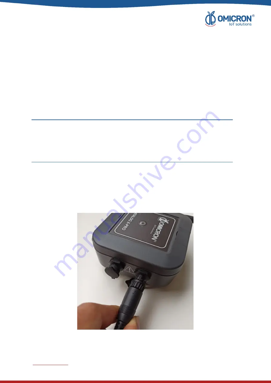
1. Align the marked guide on the sensor cable with the port.

2. Push gently into the connector until it bottoms out.

3. Screw the sensor so that it is fixed.

4. Pull slightly on the sensor and check that the sensor is securely attached to its port.

Figure 2-1 Sensor Connection

omicroniot.com

8

June

2023

Summary of Contents for DATALOG X-PRO 2.0

Page 1: ...DATALOG X PRO 2 0 IoT MULTISENSOR WIRELESS DEVICE for LoRaWAN Sigfox and GSM networks Quick Start Guide omicroniot com 1 June 2023...

Page 2: ...e record of changes per manual version Version Date Description 1 1 14 03 2023 Format change Extensive revision and correction of content Technical background information update 1 2 24 06 2023 Version...

Page 3: ...8281 Monday through Friday 7 00 a m to 5 00 p m Eastern Standard Time You can also write to solutions omicroniot com specialized personnel will discuss your application case Please have the following...

Page 4: ...ymbol The notices shown below are graded according to the previous definitions Refer to the safety messages indicated by this standard at the beginning of each section before interacting with the devi...

Page 5: ...O 9 2 2 1 Indoor use AC DC adapter connection Supplied 9 2 2 2 Outdoor use Connection to a solar panel or to an industrial power supply Not Supplied 10 2 3 Turn on the device 12 2 4 Send data via Sigf...

Page 6: ...Unauthorized changes to the product are strictly prohibited as they may unintentionally and unpredictably alter the performance and safety Unauthorized changes that interfere with the integrity of the...

Page 7: ...y and carefully before installing and setting up the product The procedures and instructions in this manual may require special precautions to ensure the safety of the personnel performing the operati...

Page 8: ...refer to Section 5 1 of the User s Manual of the Datalog X PRO NOTE A sensor can be installed in any of the three Datalog X PRO ports however once the installation is complete it is necessary to rela...

Page 9: ...supply from 12 to 24 VDC or a Solar Panel with the proper terminal Likewise and only for indoor use the user can connect the device to a 12 VDC AC DC power adapter supplied Exceeding the voltage rang...

Page 10: ...r system the output rating must be limited to 12VDC 0 5A or 24VDC 0 25A for a single Datalog X PRO In any case a 12VDC 0 5A 6W or 24VDC 0 25A 6W fuse and circuit breakers should be used between the po...

Page 11: ...Calculate the value of the fuse and the primary breaker to protect the system depending on the energy generated by the solar panel and the recommendations given by the manufacturers of the solar pane...

Page 12: ...state The equipment also turns off when it is disconnected from its power sources or is forced to do so after approaching a magnet for 10 seconds to the opposite side of the antenna To wake it up for...

Page 13: ...Figure 2 5 The LED will indicate that the magnet has been correctly approached by illuminating red After briefly approaching the magnet 2 times the main LED of the device will flash blue to show that...

Page 14: ...near the center of said clear space to leave enough margins to comfortably install its peripherals as shown below Figure 2 6 Recommended free space around the Datalog X PRO To secure the Main Unit en...

Page 15: ...e with the delivery to the Main Unit using the screws provided by the manufacturer 3 Finally fasten the Main Unit to its pole using proper mounting straps Figure 2 8 Reference example of a similar dev...

Page 16: ...ck the dashboard of the device in the Remote Monitoring Platform After accessing the remote monitoring platform supported by the manufacturer of the Datalog X PRO you can review the information sent b...

Page 17: ...Figure 2 10 Steps to view a specific Dashboard omicroniot com 17 June 2023...

Page 18: ...ers America Regional Office Omicron IoT Solutions Address Carrera 46 38 62 Off 502 Medell n Colombia Phone 57 604 2328381 WhatsApp 57 317 4365062 comercial omicroning co www omicroniot com omicroniot...

Page 19: ...2023 Omicron IoT Solutions All rights reserved omicroniot com 19 June 2023...

Reviews: