


OMEGA-VSHPe.F-IOM-2205
7
8. Secure risers to building structure as per engineer-
ing design specifications. Do not allow the risers to be
supported by the cabinets. Field supplied riser compen-
sators are required if the temperature range of the sys-
tem exceeds the expansion and contraction limit.
9. Using industry accepted soldering and brazing
standards and materials to solder or braze the riser
joints.
10. Connect supply ducts and discharge grilles.
11. Connect all ERV ducts to their corresponding con-
nections.
RISER LOOP
Servicing
To enable system flushing, servicing and balancing of
supply and return risers the following field supplied com-
ponents are required: shut
-
off valves, drain tees and
drain valves, and flow measuring devices. Refer to the
job site engineering design specifications and building
drawings for more detailed information.
Flushing & Cleaning
Once the riser system is complete the riser system must
be flushed, cleaned and re
-
filled and chemically treated.
Do not connect chassis to the water circulating system
when flushing is being conducted to prevent debris and
fouling of the water side components of the chassis (i.e.
auto balancing valve, auto shut
-
off valve, coaxial coil).
Do not flush and clean riser system with
chassis units connected. Do not allow the
flushing and cleansing solutions to flow in
the chassis water coil. Damage to water
components may occur.
Supply and return pipes must be interconnected, at a
minimum in the top and bottom units of each riser, with
factory supplied hoses to properly flush system and en-
sure adequate elimination of foreign material and clean-
ing of riser system.
1. Use only clean water to fill water circulation system.
Fill the water circulating system at the municipal water
makeup connection with all air vents opened.
2. After air vents have been sequentially closed and riser
system is primed begin water circulation of the system to
purge remaining trapped air bubbles.
3. Shut off the circulating pump and open all the drains
and vents to completely drain the system.
4. The riser system should be cleaned after the initial
flush and flushed a second time to adequately rinse the
riser system of cleaning solution.
Chassis installation is permitted once the riser system is
thoroughly flushed, cleaned, and water loop is chemical-
ly treated and commissioned by the riser treatment com-
pany and contractor.
RISER SYSTEM LOOP TEMPERATURE
Correct riser system loop temperature settings are im-
portant for optimal unit operation. Temperatures outside
of the recommended range will affect overall unit operat-
ing performance (capacity and efficiency), long term
reliability and sound performance.
Cooling Season
In cooling mode recommended riser loop temperatures
should be maintained between 85
o
F to 90
o
F. Higher riser
loop temperatures reduce unit cooling capacity and effi-
ciency, and increase sound levels.
Operation of riser loop temperatures above 110
o
F EWT
is not permitted, and sustained operation above 100
o
F
will reduce cooling capacity and may increase unit
sound levels and maintenance costs.
Heating Season
In heating mode riser loop temperatures must be main-
tained within 55
o
F to 90
o
F for standard range operation.
For Low Temperature Water (LTW) operation, riser loop
temperature are permitted down to 45
o
F with water only
risers systems. In Geothermal Range operation the sys-
tem loop must contain an appropriate glycol mixture to
protect the system from freezing the water circuit. For
Geothermal operation units must come with factory Geo-
thermal Range option. Do not operate riser system be-
low 20
o
F EWT.
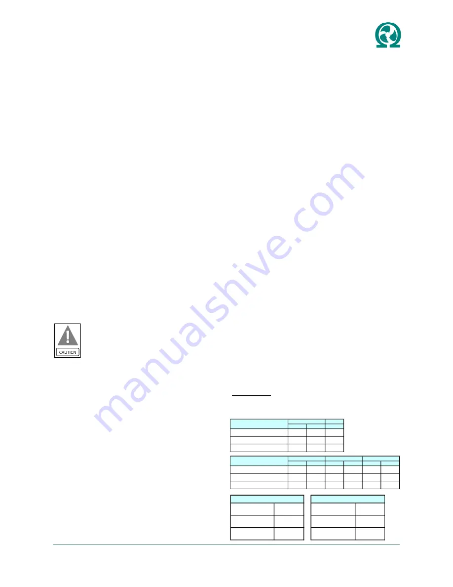
Operating Limits
Design limits can not be combined. Combining maxi-
mum or minimum limits is not allowed. This could ex-
ceed the operation and design limits of the unit.
For example: It is not allowed to combine maximum en-
tering air temperature (EAT) limits with maximum enter-
ing fluid temperature (EFT) limits.
Heating
DB
WB
DB
Std. Entering Air Temperature (EAT)
75
o
F
63
o
F
68
o
F
Min. Entering Air Temperature (EAT)
65
o
F
55
o
F
50
o
F
Max. Entering Air Temperature (EAT)
85
o
F
71
o
F
80
o
F
Cooling
Heating
Cooling
Heating
Cooling
Heating
Std. Entering Fluid Temperature (EFT)
85
o
F
70
o
F
85
o
F
55
o
F
85
o
F
60
o
F
Min. Entering Fluid Temperature (EFT)
50
o
F
55
o
F
50
o
F
45
o
F
30
o
F
20
o
F
Max. Entering Fluid Temperature (EFT)
110
o
F
90
o
F
110
o
F
90
o
F
110
o
F
90
o
F
Cooling
Air Limits
Standard Range
Low Temp Water Range
Fluid Limits
Geothermal Range
Min. CFM/Ton
300
Min. GPM/Ton
1.5
Design CFM/Ton
400
Design GPM/Ton
3
Max. CFM/Ton
450
Max. GPM/Ton
4
Fluid GPM Limits
CFM Limits


