PRODUCT OVERVIEW
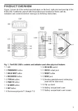
Figure 1 shows all of the controls and indicators on the front, right side, back and top of the
RDXL12SD. Familiarize yourself with the positions and functions of these controls,
indicators and connectors before moving on to the Setup Instructions.
Fig. 1. The RDXL12SD’s controls and indicators and other physical features
5
1-1 LCD
1-2
POWER/ESC
button
1-3
HOLD/NEXT
button
1-4
REC/ENTER
button
1-5
TYPE
button
1-6
PAGE
button
1-7
LOGGER
button
1-8
SET
button
1-9 Thermocouple jacks T1 through T12
1-10
SD CARD
socket
1-11
RS232
output jack
1-12
RESET
button
1-13
DC9V
jack
1-14 Housing penetration and rubber plug
(reserved for future use)
1-15 Flip-up stand
1-16 Battery compartment cover
1-17 Battery compartment cover screws
TOP
RIGHT
SIDE
BACK
FRONT
1-14
1-17
Summary of Contents for RDXL12SD
Page 17: ...15 NOTES ...

