background image

HOLDING AND STORING MEASUREMENTS

1. To hold a measured value

, press the 

HOLD/NEXT

button during the measurement.

Doing so will cause the word “HOLD” to appear at the top of the display. Pressing the

HOLD/NEXT

button again releases the hold.

2. To record and recall readings

, press the 

REC/ENTER

button while making

measurements. This will make the term “REC” appear at the top of the display. Pressing

the 

REC/ENTER

button again, briefly, will make the term “MAX” appear to the right of

“REC” and switch the display to the maximum value stored in memory during the current

recording session. Pressing the 

REC/ENTER

button again, briefly, will make the term

“MIN” appear to the right of “REC” and switch the display to the minimum value stored

during the current session.

3. To exit recording mode

, press the 

REC/ENTER

button and hold it for at least three

seconds, until the term “REC” disappears from the top line of the display. The display will

then revert to showing real-time readings.

AUTOMATIC VS. MANUAL DATA LOGGING

The RDXL12SD can automatically log data at a user-selected sampling period from 

1 second to 3,600 seconds (one hour). To view the sampling time that the instrument has

been set up to use, press the 

LOGGER

button (which has the words “Sampling time check”

stenciled below it) once. The lower left corner of the display will briefly show the term 

“SP-t”, followed by the currently programmed sampling time in seconds. To change the

sampling time, enter setup mode and perform Step 9 of the Setup Instructions.
Before entering data logging mode, remember to disable the meter’s Auto Power Off

function. To do so, enter Setup mode (as explained in the Setup Instructions on p. 6) and

select “no” during Step 6.
Also be sure that the meter either is running on fresh batteries or is being powered by AC

through a 9VDC adapter.

1. To start automatic data logging

, press the 

REC/ENTER

button once. The top line of the

display will then show the term “REC”. Pressing the 

LOGGER

button at this point will

make “REC” flash and add the flashing term “DATALOGGER” at the bottom of the display.

This indicates that the instrument is sampling measurements at the programmed rate

and storing the readings and their time stamps in memory.

2. To pause automatic data logging

, press the 

LOGGER

button once; this will make

the flashing term “LOGGER” disappear from the bottom of the display and change the

term “REC” from flashing to constant. Pressing the 

LOGGER

button again resumes

automatic data logging.

10

Summary of Contents for RDXL12SD

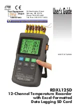
Page 1: ...annel Temperature Recorder with Excel Formatted Data Logging SD Card MADE IN TAIWAN User sGuide 99 Washington Street Melrose MA 02176 Phone 781 665 1400 Toll Free 1 800 517 8431 Visit us at www TestEquipmentDepot com ...

Page 2: ...U S A The information contained in this document is believed to be correct but OMEGA accepts no liability for any errors it contains and reserves the right to alter specifications without notice ...

Page 3: ...12 CHANNEL TEMPERATURE RECORDER WITH EXCEL FORMATTED DATA LOGGING SD CARD USER S MANUAL RDXL12SD Please read this manual carefully and thoroughly before using this product ...

Page 4: ... 5 Setup Instructions 6 8 Adjusting Thermcouple Offsets 8 Operating Instructions 9 12 Normal Operation 9 Holding and Storing Measurements 10 Automatic vs Manual Data Logging 10 11 Transferring Data from the SD Card to a Computer 12 Specifications 13 Maintenance Troubleshooting Tips 14 2 ...

Page 5: ...wo K type thermocouples included with the instrument have a measurement range of 50 to 500 F 45 to 260 F These very wide ranges plus a fast response time and a low price tag suit thermocouple thermometers for a variety of commercial and industrial tasks requiring measurement of very high and low temperatures Examples include applications in the food and chemical processing industries HVAC heating ...

Page 6: ...n diagonal front panel green backlit LCD is easy to read Displays maximum and minimum readings and holds any reading Automatically logs measurements at sampling time settable from one second to one hour Also supports manual data logging and changing of SD card storage location Outputs Excel compatible data logs Accepts SD memory cards of up to 16 GB capacity Auto power off function that can be dis...

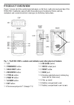
Page 7: ...rols and indicators and other physical features 5 1 1 LCD 1 2 POWER ESC button 1 3 HOLD NEXT button 1 4 REC ENTER button 1 5 TYPE button 1 6 PAGE button 1 7 LOGGER button 1 8 SET button 1 9 Thermocouple jacks T1 through T12 1 10 SD CARD socket 1 11 RS232 output jack 1 12 RESET button 1 13 DC9V jack 1 14 Housing penetration and rubber plug reserved for future use 1 15 Flip up stand 1 16 Battery com...

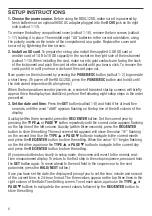
Page 8: ...er presented 3 Set the date and time Press the SET button callout 1 8 and hold it for at least five seconds until the word dAtE appears flashing on the top line of the left column of the display Quickly within three seconds press the REC ENTER button Set the current year by pressing the TYPE or PAGE button repeatedly until the correct value appears flashing on the top line of the left column Quick...

Page 9: ...ording and enabled or disabled the function the display will show the term dEC in the third row of the left column Press the REC ENTER button This will cause the term dEC to appear in the lower right corner below the term USA Use the TYPE or PAGE button to make USA or Euro as desired appear above dEC and then press the REC ENTER button to store the selection as the default 6 Enable or disable auto...

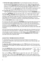
Page 10: ...the beeper is enabled To confirm that you want to begin the erasure formatting procedure press the REC ENTER button Ent will then flash several times and the instrument will sound another three beeps to confirm that the SD card has been erased and formatted Once the SD card has been formatted or not the display will return to flashing the first of the eight steps in the setup sequence setting the ...

Page 11: ...E button once To return the display to Channels T1 through T8 press the PAGE button again 3 To use J T E R or S type thermocouples to measure up to 12 channels of temperature first press the TYPE button as many times as necessary until the letter of the thermocouple type you are using appears on the top line of the display Then plug one to 12 of the optional accessories into the jacks on the top o...

Page 12: ...sampling time that the instrument has been set up to use press the LOGGER button which has the words Sampling time check stenciled below it once The lower left corner of the display will briefly show the term SP t followed by the currently programmed sampling time in seconds To change the sampling time enter setup mode and perform Step 9 of the Setup Instructions Before entering data logging mode ...

Page 13: ...ttons to change the flashing value to any number between 1 and 99 Once you have chosen the storage location press the REC ENTER button to save the setting This will cause the value to stop flashing and the P to return 6 To end manual data logging press the REC ENTER button and hold it for at least three seconds This action will cause REC to disappear from the top line of the display 7 To execute t...

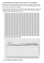
Page 14: ...ur computer either directly if it has an SD card slot or through an SD card reader Because the files containing time stamped data logs have the file extension xls they open in Microsoft s Excel application Figures 2 and 3 show two kinds of Excel presentations a data only screen and a graphics only screen 12 Fig 2 Typical Excel data only screen Fig 3 Typical Excel graphics only screen ...

Page 15: ... type thermocouples 0 1 F or C below 1000ºF 1 F or C above 1000 F With R and S types 1 F or C Sampling time options 0 1 2 5 10 30 60 120 300 600 1800 or 3600 seconds Settable parameters Date time decimal point or comma decimal division auto power off beep sound loop data recording enable disable and start stop times temperature unit sampling time thermocouple type and offset Storable readings Maxi...

Page 16: ...ews that hold the battery compartment cover in place as explained in Step 1 of the Setup Instructions on p 6 After inserting fresh batteries in the correct orientation replace the cover and tighten the screws to secure it If the meter freezes like a computer and buttons become unresponsive try resetting the instrument by pushing the RESET button on its right side callout 1 12 of Fig 1 with the end...

Page 17: ...15 NOTES ...
Page 18: ...NOTES 16 99 Washington Street Melrose MA 02176 Phone 781 665 1400 Toll Free 1 800 517 8431 Visit us at www TestEquipmentDepot com ...

Page 19: ...otherwise shall not exceed the purchase price of the component upon which liability is based In no event shall OMEGA be liable for consequential incidental or special damages CONDITIONS Equipment sold by OMEGA is not intended to be used nor shall it be used 1 as a Basic Component under 10 CFR 21 NRC used in or with any nuclear installation or activity or 2 in medical applications or used on humans...

Page 20: ... M U Totalizers Batch Controllers pH CONDUCTIVITY M U pH Electrodes Testers Accessories M U Benchtop Laboratory Meters M U Controllers Calibrators Simulators Pumps M U Industrial pH Conductivity Equipment DATA ACQUISITION M U Data Acquisition Engineering Software M U Communications Based Acquisition Systems M U Plug in Cards for Apple IBM Compatibles M U Data Logging Systems M U Recorders Printers...

Reviews: