background image

OmegaView Version 1.4x 


Channels to Log

:  This option only appears if the device has more than one channel.  You can elect to disable 

unused logger channels.  When a channel is disabled, its memory is allocated to the other channels, increasing 
the total logging time.  The total logging time will be reflected in the 

Sample Interval

 window.  Depending on 

the logger, some channels are required and cannot be disabled.  Channels that can not be disabled are grayed out 
and can not be unchecked.  For instance, in the picture above, the Temperature channel is required to record 
Relative Humidity, so the Temperature channel cannot be disabled.  At least one channel must be enabled for 
logging. 


Alarm Setup

:  Click this button to open the 

Alarm Setup Window

. 

Custom Interval Setup 

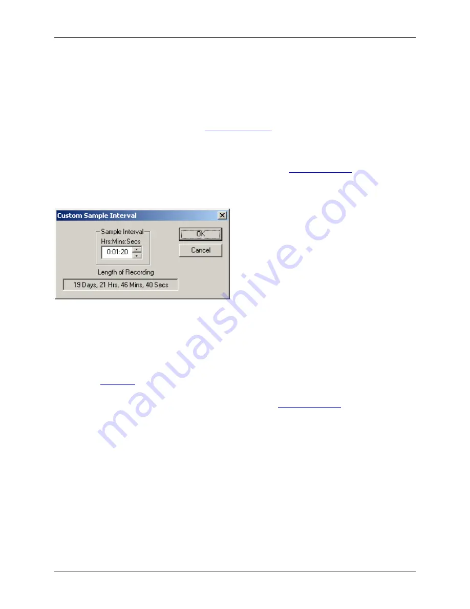
Commonly used intervals are predefined in the 

Sample Interval

 box in the 

Logger Setup screen

 A custom interval 

can also be defined by the user.  To do this, click on the 

Custom Interval

 button in the Logger Setup screen.  The 

custom interval window is shown below.  You can select a custom logging interval using this window. 


In the window above, the sampling interval was set to 1 minute, 20 seconds, to allow about 20 days of recording. 

Alarm Setup 

Alarms are used to indicate if the data inside the logger exceeded a user specified threshold.  This can be an 
indication that an important event has occurred.  The logger will indicate that an alarm condition has occurred by 
displaying the 

Alarm icon

 Once an alarm condition has occurred, the alarm icon will remain turned On for the 

duration of the logging session to indicated that data stored in the device memory has alarms in it. 

To get to the 

Alarm Setup

 window, click the 

Alarm Setup

 button in the 

Logger Setup screen

 The 

Alarm Setup


windows allows you to set high and/or low alarm thresholds for each data channel, or disable these alarms.  Alarms 
are set by entering the thresholds as shown in the window below. 


Summary of Contents for OM-70 Series

Page 1: ...omega com e mail info omega com For latest product manuals omegamanual info OM 70 SERIES Data Logger Interface Software Extended Warranty Program SM MADE IN Shop online at User sGuide...

Page 2: ...n Germany TEL 49 0 7056 9398 0 FAX 49 0 7056 9398 29 Toll Free in Germany 0800 639 7678 e mail info omega de United Kingdom One Omega Drive River Bend Technology Centre ISO 9001 Certified Northbank Ir...

Page 3: ...oom Feature 8 Data Listing Window 9 Data Summary and Statistics 9 Exporting Logger Data 11 Printing the Logger Data 12 Calibrating the Logger 12 Setting the Calibration Password 13 Setting the Logger...

Page 4: ...nd click on the icon on the toolbar The logger status screen should now be displayed Note The Windows operating system can not handle USB devices being unplugged and plugged back too fast When unplugg...

Page 5: ...list you can set a custom interval using this button Overwrite oldest samples when full Check this box to have the logger continuously record data overwriting oldest recorded data When this box is no...

Page 6: ...stom interval can also be defined by the user To do this click on the Custom Interval button in the Logger Setup screen The custom interval window is shown below You can select a custom logging interv...

Page 7: ...status screen is separated into three panes General Logger Status and Data In Memory Pane Logger State shows the internal state of the logger o Power Save Mode This mode is entered when the logger idl...

Page 8: ...ery is replaced when this indicator reaches yellow When this indicator reaches red logging becomes unreliable and the battery should be replaced before starting a new logging session Logging Started A...

Page 9: ...ing Logger Data To get the sampled data from your logger connect the logger to your computer and click the button on the toolbar Once the data is transferred from the logger to your PC the data graph...

Page 10: ...t your device to collect data once every minute the software will perform a download once a minute Of course the device has to be connected to your computer while the Auto Data Load mode is active Whe...

Page 11: ...vate the zoom Clicking the right mouse button unzooms the graph one level See Using the Zoom Feature section for more details The button turns ON and OFF the marks at the data points The button connec...

Page 12: ...axis Data Listing Window The data listing window is shown below The Data pane lists the data samples collected by the logging device The column width of each column is adjustable by using the left mo...

Page 13: ...tical and food industries as a simplified way of expressing the overall effects of temperature fluctuation during storage and transit of perishable goods The formula used to calculate the MKT in Kelvi...

Page 14: ...ile exported to Microsoft Excel is an Excel csv file The easiest way to open this file in Excel is to just double click on the created file When you first open the csv file in Excel the Date Time colu...

Page 15: ...ty to perform a single point offset calibration This calibration can be used to increase the accuracy of your device for a restricted data range For instance if your application calls for logging temp...

Page 16: ...sor in a regulated chamber 3 Wait for your reference instrument and the reading in the Logger Reading box to stabilize 4 Enter the reading from your reference instrument in the Reference Instrument bo...

Page 17: ...dated every second During logging the time stamps of the data samples are set by this clock When the logger is in power down state the real time clock is not running When the real time clock is stoppe...

Page 18: ...Operating System Compatibility Windows 2000 Windows XP Windows Vista and above Not compatible with Windows NT Windows 95 Windows 98 or Windows ME System Requirements 800 x 600 screen resolution 1 fre...

Page 19: ......

Page 20: ...mage to the internal electronics The OM 72 sensor is condensation resistant but should not be submerged in liquid for an extended period of time The OM 74 thermocouple sensor can be used in any enviro...

Page 21: ...temperature and or humidity display shows the recorded value at that time The hours and minutes separator will not blink in this mode The logger will automatically exit the browse mode when the browsi...

Page 22: ...ogger is also displayed by the PC software in the Status screen and the Data Summary pane Replacing the Logger Battery OM 71 OM 72 and OM 73 loggers use a single Lithium CR2032 coin cell OM 74 uses th...

Page 23: ...e display can fall out 5 Carefully remove the logger board from the case 6 Using a small screw driver gently push the battery out the holder Once the battery is part way out you can use your fingers t...

Page 24: ...e 5 F to 160 F 20 C to 70 C OM 72 External Probe Temperature 40 F to 176 F 40 C to 80 C OM 72 External Probe Length 6ft 1 8m Storage Temperature 20 F to 175 F 30 C to 80 C Time Accuracy 100ppm 75 F Te...

Page 25: ...ion 0 2 F 0 1 C Thermocouple Impedance 50 Ohms maximum for specified accuracy Cold Junction Temperature Accuracy 0 5 F 0 3 C User Calibration User single point offset calibration is available through...

Page 26: ...to 2372 F 200 C to 1300 C T 1 3 F 0 7 C 328 F to 752 F 200 C to 400 C S 5 0 F 2 8 C 58 F to 3200 F 50 C to 1760 C R 5 0 F 2 8 C 58 F to 3200 F 50 C to 1760 C B 6 0 F 3 3 C 68 F to 3308 F 20 C to 1820...

Page 27: ...therwise shall not exceed the purchase price of the component upon which liability is based In no event shall OMEGA be liable for consequential incidental or special damages CONDITIONS Equipment sold...

Page 28: ...ity Indicators Turbine Paddlewheel Systems Totalizers Batch Controllers pH CONDUCTIVITY pH Electrodes Testers Accessories Benchtop Laboratory Meters Controllers Calibrators Simulators Pumps Industrial...

Reviews: