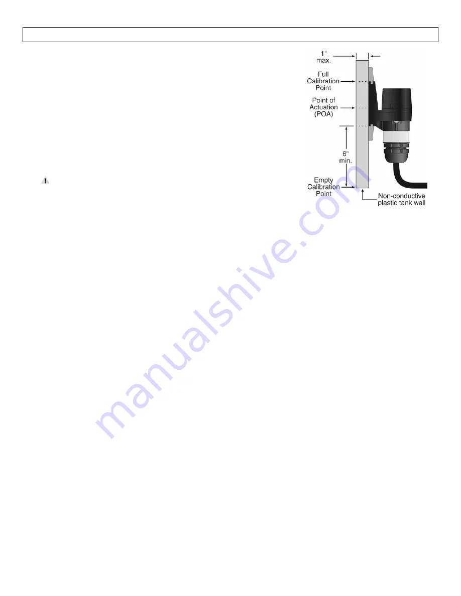
background image

14


MAINTENANCE


Step


Seven


Checking


the


Point


of


Actuation:


Raise


the


fluid


level


to


the


point


where


the


sensor


sends


a


“wet”


signal


(Input


LED


will


turn


Amber


on


OMEGA


ENGINEERING


controllers).


The


“dry”


signal


should


be


sent


when


the


fluid


level


is


lowered


(Input


LED


will


turn


Green


on


OMEGA


ENGINEERING


controllers).


The


actual


Point


of


Actuation


(POA)


depends


on


many


variables,


including


the


thickness


of


the


wall


and


the


dielectric


value


of


the


liquid.


For


example,


thicker


tank


walls


can


raise


the


POA


while


thinner


walls


could


lower


the


POA.


If


the


POA


needs


to


be


changed,


measure


the


distance


and


remount


the


sensor


in


a


new


location.


Do


not


attempt


to


change


the


Point


of


Actuation


by


intentional


miscalibration.


If


the


sensor


does


not


signal


wet


and


dry


reliably,


it


may


be


that:


the


dielectric


constant


of


the


application


fluid


is


too


low


the


tank


wall


is


too


thick


for


the


application


fluid


there


are


static


or


other


electrical


charges


in


the


fluid


metal


objects


are


within


6"


of


the


sensor


calibration


was


performed


incorrectly


Try


the


calibration


procedure


again,


after


making


corrections


if


possible.


If


the


full


and


empty


states


are


too


similar


dielectrically,


it


may


not


be


possible


to


use


a


capacitance


sensor.


Testing


the


Sensor:


1.


Power:


Apply


power


to


sensor,


by


connecting


power


to


the


controller


and/or


power


supply.


2.


Full


condition:


Fill


the


tank


with


the


application


liquid,


by


filling


the


tank


up


to


the


sensor’s


point


of


actuation.


3.


Test:


With


the


sensor


being


fluctuated


between


wet


and


dry


states,


use


a


multimeter


to


ensure


that


the


correct


signals


are


being


produced


by


the


LVP

51

R


level


switch,


or


observe


the


sensor


indicator


light


in


the


controller.


4.


Point


of


Actuation:


Observe


the


point


at


which


the


rising


or


falling


fluid


level


causes


the


sensor


to


change


state,


and


move


the


installation


of


the


sensor


if


necessary.


Maintenance:


The


LVP

51

R


level


switch


itself


requires


no


periodic


maintenance


except


cleaning


as


required.


However,


periodically


clean


any


coating


or


scaling


on


the


tank


wall


the


sensor


is


attached


to


and


check


the


calibration.


It


is


the


responsibility


of


the


user


to


determine


the


appropriate


maintenance


schedule,


based


on


the


specific


characteristics


of


the


application


liquids.


In


addition,


any


dripping


or


condensation


between


the


sensor


and


the


tank


wall


fitting


may


need


to


be


periodically


cleaned


to


maintain


accuracy.


Summary of Contents for LVP-51-R

Page 1: ...1 ...

Page 2: ...2 ...

Page 3: ...pment The sensor s operation and point of actuation may vary based on the dielectric properties of various application liquids tank materials and thicknesses The LVP 51 R sensor is intended to be used with liquids with a dielectric value between 20 and 80 Due to its user calibration capability it may be able to detect liquids below a dielectric constant of 20 under certain conditions but this must...

Page 4: ... type 1 SPST relay Contact rating 60 VA 1A maximum Contact output Selectable NO NC Process temp F 40 to 176 C 40 to 80 Enclosure rating NEMA 4X IP65 Enclosure mat PSO Conduit entrance Single 1 2 NPT Bracket material LVP 92 PP LVP 91 PE Bracket mounting 3M adhesive plastic thermal weld Cable jacket mat PP Cable type 4 conductor 22 AWG shielded Cable length Standard 10 3m Classification General purp...

Page 5: ...t The LVP 51 R sensor may be mounted in the PE LVP 91 or PP LVP 92 bracket Make sure that the fitting is compatible with the tank it will be applied to Material Compatibility The sensor itself is not designed to be immersed It should be mounted in such a way that it does not normally come into contact with fluid Its case is made out of Polysulfone PSO Refer to an industry reference such as the Com...

Page 6: ...on Dielectric Constants NOTE Liquids with a conductivity value 100 µS cm are fine if coating is not an issue Liquids with a dielectric constant less than 20 will not be detected by an LVP 51 R level switch depending on conditions Acetone 21 Acetoaldehyde 22 2 Acetyl methyl hexyl ketone 28 Alcohol 16 to 31 Ammonia 15 to 25 Acetic acid 4 1 to 6 2 Butyl chloride 9 6 Barium chloride 9 to 11 Benzene 2 ...

Page 7: ...a seal between the sensor and the tank wall and will hold it in place during testing and installation If desired the sensor may be installed temporarily without welding the fitting to the wall If several different locations must be tried before permanent installation use double sided foam stick tape designed for PP or PE 4 After the sensor has been tested to verify the POA weld glass or strap the ...

Page 8: ...oval and or maintenance of the sensor The cable length may be extended up to a maximum of 1000 feet using a well insulated 14 to 20 gauge shielded four conductor cable Wire Stripping Using a 10 gauge wire stripper carefully remove the outer layer of insulation from the last 1 1 4 of the sensor s cable Unwrap and discard the exposed foil shield from around the signal wires leaving the drain wire at...

Page 9: ...60 VDC All models LVP 51 R uses the relay and features 4 wires red black white and green and a shield wire The NO NC status is set by the polarity o f the voltage feeding the red and black wires The green wire is the common for the relay and the white wire is the NO or NC depending on the polarity of red and black Normally Open Wiring Normally Closed Wiring ...

Page 10: ... RC for AC circuits Catch Diode Always use stepper relays between the sensor and external loads For DC circuits use a catch diode such as 1N4148 shown on left Refer to the following circuits for RC network assembly and installation Choose R and C as follows R 0 5 to 1 Ohms for each volt across the contacts C 0 5 to 1 μF for each amp through closed contacts Notes 1 Use capacitors rated for 250 VAC ...

Page 11: ...either the Green or White wires Complete the circuit by connecting the Green to VDC power or White to VDC power see illustration below Sensor Power RED BLK wires 36 VDC Max 5 1mA Dry 20 1mA Wet Relay Rating GRN WHT wires 60 VA Switching a Normally Open AC Load The Red wire connects to Positive of the DC power supply and the Black wire connects to Negative The LOAD can be attached to the Green wire...

Page 12: ...ile the White wire is connected to the LOAD Jumper the LOAD to the Negative to complete the circuit Sensor Power RED BLK wires 36 VDC Max 5 1mA Dry 20 1mA Wet Relay Rating GRN WHT wires 60 VA Normally Open DC Load as a N Channel Output The Red wire connects to Positive of the power supply and the Black wire connects to Negative The White wire is jumped to the Black wire while the Green wire is con...

Page 13: ...he sensor Insert a small screwdriver into the small slot at the edge of the cap and gently pry upwards 2 Looking down you will see a small three position switch and two trim pots marked Full and Empty You may start with whatever state the tank is in 3 Full state With the tank filled to the top of the sensor set the switch to the Full position right Make sure your hands or any other objects are not...

Page 14: ...corrections if possible If the full and empty states are too similar dielectrically it may not be possible to use a capacitance sensor Testing the Sensor 1 Power Apply power to sensor by connecting power to the controller and or power supply 2 Full condition Fill the tank with the application liquid by filling the tank up to the sensor s point of actuation 3 Test With the sensor being fluctuated b...

Page 15: ...15 ...

Page 16: ...16 ...

Reviews: