11
www.omega.com e-mail: [email protected]
Handling
When cleaning the rod use a soft brush or any
other similar object.
Probes:
Periodic visual inspection of the probe is required
to check for corrosion or deposit build-up. If
deposits are found, clean the sensor to ensure
optimum performance.
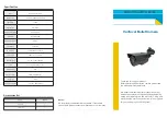
The probe should not be dropped or suffer any
impact or fall that could damage the electronics or
the plastic tip of the probe (Fig. 4 and 5).
Seal the thread with Teflon tape before
installation (Fig. 1).
Do not turn or handle by the housing when
tightening the process connection. However, the
housing is suitable to be reoriented by once the
process connection has been tighten.(Fig. 2).
Use the correct tool during installation (Fig. 3)
Fig. 5
Fig. 4
Fig. 3
Fig. 2
Fig. 1
Summary of Contents for LVCN6000 series
Page 1: ...LVCN6000 7000 Series Capacitive Point Level Detection...
Page 2: ......
Page 15: ......
Page 16: ......