


FTB300 Series
Page 3
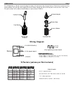
Wiring Diagram
Foot Strainer
Strainer Adapter
Strainer Body
Screen Strainer
Suction Tubing
Part Number
FPUSV-V
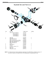
Exploded View
Your FTB300 flow verification sensor package includes a Foot Strainer (see diagram below). This strainer will prevent any
small particles from entering and clogging the Sensor Body. Diaphragm pumps will require a strainer and a check valve.
The part number for the strainer that includes a check valve is FPUSV-V.
Sensor
+
_
Red
0v dc
(True digital Square-wave output)
+5v dc
Bare
Black
(Ground)
Sensor connections:
Input voltage (vdc) 8 to 28 vdc
Output voltage (v) “high state” 4 80 v dc min (5 vdc normal)
Output voltage (v) “low state” 0 2v dc max
+ 5 Vdc (signal output)
8 to 28 Vdc (Positive)
K-Factors (pulses per fluid volume)
30-300
1
100-1000
2
200-2000
3
300-3000
4
500-5000
5
700-7000
6
181,336
81,509
42,051
25,153
15,737
9,375
Flow Range
(ml/min)
Body
Size
Pulses per
Gallon
21,535
13,752
6,646
4,157
2,477
Pulses per
Liter
47,909
Useful formulas
60 / K = rate scale factor
rate scale factor x Hz = flow rate in volume per minute
1 / K = total scale factor
total scale factor x n pulses = total volume
Summary of Contents for FTB300 Series
Page 1: ......
Page 2: ......
Page 6: ...Notes Page 6 FTB300 Series...
Page 7: ......
Page 8: ......