Safe Fleet inView 360 Fusion, Calibration Manual
The Safe Fleet inView 360 Fusion Calibration Manual is available for free download on manualshive.com. This essential manual provides detailed instructions on how to calibrate your inView 360 Fusion system, ensuring optimal performance and safety. Download your copy now to keep your fleet operating at its best.
Share
Download


Reviews:
No comments
Related manuals for inView 360 Fusion

2011 Tribute
Brand: Mazda Pages: 4
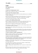
S5
Brand: JAC Pages: 70

202
Brand: E-Mu Pages: 52

2-wire Series
Brand: 2easy Pages: 17

TV2
Brand: 2DI Pages: 38

TV2
Brand: 2DI Pages: 3

Horus
Brand: GCE Pages: 16

Elite XL-1208
Brand: GCC Technologies Pages: 12

23A00-1
Brand: HAI Pages: 2

Unicorn 3001
Brand: Hanlong Pages: 26

DS-100
Brand: KDS Pages: 72

NNC994S - Genius Prestige - Convection Microwave...
Brand: Panasonic Pages: 1

NPL-TV 7874 DIGITAL
Brand: Napoli Pages: 20

2020168
Brand: GE Pages: 2

2 SD Card Memory Module NI 9802
Brand: National Instruments Pages: 16

MOLLE PANELS RAM 2500
Brand: PUTCO Pages: 4

Portilo 350000
Brand: Westfalia Pages: 18

32 025 888
Brand: Saab Pages: 3


