NOTICE:
Be sure all tools and personnel are clear
before lowering load. Only attachments and/or
adapters supplied by the manufacturer shall be used.
Lift only on areas of the vehicle as specified by the
vehicle manufacturer.
!
WARNING
•
Study, understand, and follow
all printed materials
provided with/on this product before use.
•
Do not
exceed rated capacity.
•
This is a lifting device only! Immediately
after
lifting, support the load with
a pair
of appropriately
rated jack stands
•
Only
attachments and/or adapters supplied by the
manufacturer shall be used.
• Use only on hard, level surface.
• Lift only on areas of the vehicle as specified by
the vehicle manufacturer.
• Never wire, clamp or otherwise disable the lift
control valve to function by other than operator's
hand.
• No alterations shall be made to this product.
• Failure to heed these markings may result in
personal injury and/or property damage.
To avoid
crushing and related injuries
:
•
Never
work on, under or around a load supported
only by hydraulic jack.
•
Always
use adequately rated jack stands.
• Chock each unlifted tire in both directions.
•
Do not
use this device to lift, level, lower, support nor
move a house, mobile home, travel trailer, camper or
any building structure.
•
Be alert
and
sober
when using this product. Do not
operate under the influence of drugs or alcohol.
!
WARNING
X
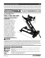
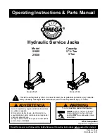
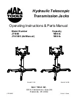
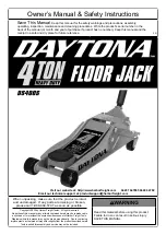
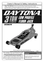
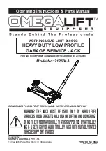
OPERATION
Raising the Ram Plunger
1. Assemble handle, ensure that spring clips align with slots.
2. Place vehicle in the park, with emergency brake on and wheel securely chocked to prevent inadvertent vehicle
movement.
3. Locate and close release valve by turning handle clockwise until firm resistance is felt to further thread
engagement.
4. Verify lift point, center jack saddle under lift point.
5. Squeeze the lift control valve in order to raise saddle to contact lift point. To lift, continue pumping until load reaches
desired height.
6.
Immediately
secure lifted load with appropriately rated jack stands.
WARNING:
Use only the handle provided by jack manufacturer. The handle provided with this jack will safely
engage the release valve. If handle is worn, operates abnormally, or will not positively engage the release
valve,
STOP
, discontinue use of the jack until a factory replacement handle can be acquired.
WARNING:
Do not use an extender on the air hose or the operating handle.
Lowering
WARNING:
Make certain that all personnel are clear of the load before lowering.
Control
the rate of descent
of the load
at all times
. The
more
you open the release valve, the
faster
the load descends.
1. Raise load high enough to clear the jack stands, then carefully remove jack stands (
always
used in pairs).
2. Slowly turn the handle counter-clockwise, but no more than 1/2 turn. If the load fails to lower:
a. Use another jack to raise the vehicle high enough to reinstall jack stands.
b. Remove the affected jack and then the stands.
c. Lower the load by turning the release valve counter-clockwise, but no more than 1/2 turn.
3. After removing jack from under the load, push ram and handle sleeve down to reduce exposure to rust and
contamination.
!
!
!
3