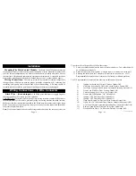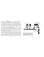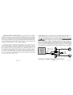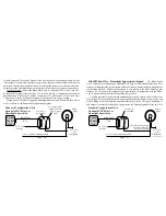
Violet Wire - (Positive Door Trigger):
The Violet wire's functions are identical
to the Green Door Trigger wire, with the sole exception that it is an open door input to the
control module for vehicles having Positive 12 volt door pin switches.
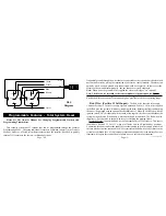
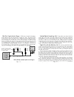
CONNECTION: Connect the Violet wire to a wire in the vehicle which is common to
all the door pin switches. The correct wire for this type of dome light/door jamb pin switch
system will have 12 volts present when the doors are opened, and chassis ground when the
doors are closed. The correct wire will show this change when any of the doors are opened.
Note: If the car has a delay dome light the Circuit Bypass feature will allow the system to
be armed from the transmitter instantly and will start protecting the Violet wire circuit when
the dome light turns off. In Last Door Arming mode, the system arms 30 seconds after the
dome light turns off.
1
1
1
1
1
1
1
This Is
The Correct
Trigger Wire.
Driver
Pin
Switch
Typical Positive
Dome Light System.
1234567890123
1234567890123
1234567890123
1234567890123
1234567890123
1234567890123
1234567890123
1234567890123
1234567890123
1234567890123
1234567890123
1234567890123
1234567890123
1234567890123
To Chassis
Ground
Dome
Light
To Constant
12 Volt
Note: The Driver Pin Switch Often Will Have An Extra
Wire . This Circuit Will Trigger The Security System, But Only
From The Driver's Door, And Is The Incorrect Trigger Wire.
Passenger
Pin
Switch
Page - 17
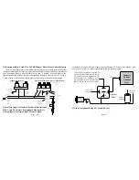
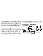
If the optional Domelight
Supervision output will be
utilized, see Page 20 for
further information.
Page - 28
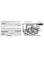
to identify a doorlock system is to examine the doorlock switch's wiring. The following
sections will discuss the types of doorlock systems found and the available optional
interfaces.
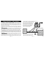
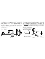
3 Wire Negative Pulse Systems:
This power doorlock system is indicated by the
presence of three wires at the switch. Of these, one will show constant ground, regardless
of whether the switch is being operated or not (at rest). Of the remaining two wires, one will
show ground when the switch is pushed to the "lock" position, and the other wire will show
ground when the switch is pushed to the "unlock" position. With the switch at rest, these two
wires will read voltage, usually 12 volt positive but in some cases less. The wires from the
switches operate doorlock relays or a doorlock control unit with built-in relays. The correct
connection point is between the switches and the relays.
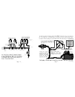
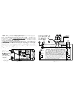
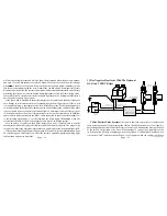
An optional harness is available (model DLP-N3) which allows direct connection
between the security system and the doorlocks. Some doorlock systems, however, require
more than the 500ma ground output that the security system's control module can
accommodate. In these cases the optional model DLS and two relays must be used. When
driver's door unlock priority is desired, the correct interface is the DLS-3 (Pages 36-39).
Green Wire To Vehicle Lock Wire
Blue Wire To Vehicle Unlock Wire
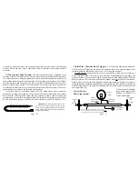
Model DLP-N3 -Three pin connector with two
24" wires. Allows direct connection of the security
system's negative pulse outputs directly to a vehicle's
negative pulse doorlocks or to facilitate custom hard-
wiring of optional relays.
Summary of Contents for INSTALLATION MANUAL
Page 2: ...Page 43 Page 2...


