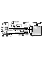
background image

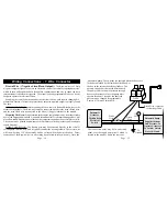
vehicle's horn wire is identified, probe the wire with a standard  test light connected to
Negative chassis ground.   If the horn honks when probed, a direct connection may be made.
If not, use the following diagram to configure an optional  relay.  CAUTION! This is one
of the few uses left for a standard test light in a modern vehicle!   Use a digital multimeter
(DMM) to identify the horn wire first.  Probing an Airbag circuit with a standard test light
can cause the Airbag to deploy!  
One alternative is to disconnect the horns, then operate
the horn switch.  A clicking sound from the vehicle will confirm the presence of a horn
relay.  Another alternative is to check a wiring schematic of the vehicle in question.

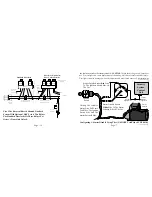
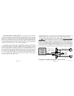
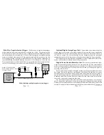
Configuring An Optional Relay:  The Brown Siren/Horn output wire has a 1 Amp

capacity, which, if exceeded, can damage the security system control module.  Certain
situations, among them multiple sirens or a vehicle which lacks a horn relay, an optional
SPDT relay is required.

Page - 11

Page - 34

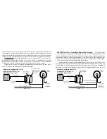
DLS

Relay

Relay

+

DLS Blue Wire To DS-2 Red Wire

DLS Green Wire To DS-2 Blue Wire

 DLS Connector
Plugs Into Alarm

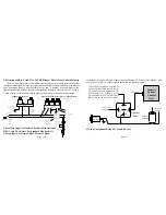
Note: Use this
diagram when
adding  actuators
to a vehicle not
equipped with
factory power
door locks.

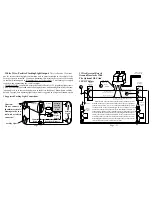
Some vehicles have a type of power doorlock system in which mechanically locking and
unlocking the driver's door will operate an electrical switch in the door which supplies
voltage to actuators in the other doors. There is no actuator in the driver's door, only a switch.
An indication of  this type
of power doorlock system
is when the driver door
key will operate the pass-
enger door, but the pass-
enger side will not oper-
ate the driver door.

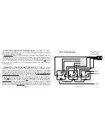
Adding The Optional DS-2 Actuator And The DLS And 2 Relays:

DLS Violet

Wire To

   12 Volt

Mercedes Vacuum Doorlocks And Optional DLS-V And Two SPDT

Relays: 

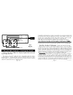
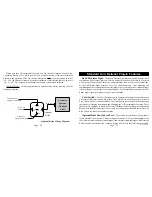
This doorlock system is used on older Mercedes Benz vehicles and consists of

electrical switches (built into pneumatic actuators) which supply 12 volts or ground to a

DLS Brown And

      White Wires

              Connect To

 Chassis Ground

To vehicle's
  horn wire.


 30

     86    87a    85

              87


     Constant

      (+) 12 Volt


 Brown wire

   from module


(+) or (-) as

needed to operate
the Siren/Horns

Optional Relay Wiring Diagram

Summary of Contents for INSTALLATION MANUAL

Page 1: ...apply to any product damaged by accident physical or electrical misuse or abuse improper installation alteration any use contrary to its intended function unauthorized service fire flood lightning or...

Page 2: ...Page 43 Page 2...
Page 3: ...or An Optional Power Doorlock Interface 27 40 23 PROGRAMMABLE FEATURES ProgrammingFeaturesAndTotalSystemReset 40 42 Page 3 Page 42 14 Two Unlock Pulses With 8 Second Setting Default OFF 15 3 Or 45 Sec...

Page 4: ...or grease away from the connection point until the metal is bright and clean Note If the control module has an insufficient ground connection the security system can Wiring Connections 5 Wire Connect...

Page 5: ...viced without the system being activated if the battery is disconnected and reconnected The Red wire also supplies 12 Volt Positive to the built in relay for flashing the parking lights CONNECTION Con...

Page 6: ...an armed state This output supplies Negative Ground to one side of the relay s coil The other side of the relay coil will be supplied with Positive Voltage from the ignition switch but only if the ig...

Page 7: ...odily injury Test lights can also damage on board computers and associated sensors The starter wire Continued Next Page 30 86 87a 85 87 Control Module Orange Wire Socket Orange Wire Continued Next Pag...

Page 8: ...tay grounded for as long as the small transmitter button is depressed for up to 15 seconds Also the security system will automatically disarm unlock the doors and illuminate the exterior lights on for...

Page 9: ...e most universal interfacewhichallowsthesecuritysystemtolockthevehicle sdoors unlockonlythedriver s upon disarming driver s door unlock priority and if desired a second press of the transmitter s butt...

Page 10: ...ine compartment and not be accessible to a thief The siren must be pointed downward to avoid moisture collecting inside it and to enhance sound dispersal HORN CONNECTION The Brown wire may be connecte...

Page 11: ...S Relay Relay DLS Blue Wire To DS 2 Red Wire DLS Green Wire To DS 2 Blue Wire DLS Connector Plugs Into Alarm Note Use this diagram when adding actuators to a vehicle not equipped with factory power do...

Page 12: ...e Rear Body Harness Head Light Switch Junction Block Dash Lights Dimmer Caution Do not connect to the dimmer circuit Damage to the con trol unit or vehicle can occur Parking Lights Security System Con...

Page 13: ...eostat or illumination control module and possibly cause damage to the vehicle or alarm control unit Also if the White wire touches chassis ground the Printed Circuit Board and on board relay may be d...

Page 14: ...ation of the system sounding the siren and flashing the exterior and interior lights if in an armed state If the Last Door Arming and Automatic Rearming features are utilized after turning off the ign...

Page 15: ...ch Typical Grounding Type Dome Light System Dome Light Note TheDriverPinSwitchOftenWillHaveAn ExtraWireThatGoesToTheIgnitionKeyWarn ing Chime This Circuit Will Trigger The Secu rity System But Only Fr...

Page 16: ...ior door handles or to the latching mechanism A car that features the dome lights illuminating when the exterior door handle is lifted is an example of this type of switching system Also be aware of v...

Page 17: ...Supervision output will be utilized see Page 20 for further information Page 28 to identify a doorlock system is to examine the doorlock switch s wiring The following sections will discuss the types o...

Page 18: ...l relay coils only a first negative pulse for driver door unlock and a second negative pulse for unlocking all other doors The doorlock interface needed will depend upon the type of power doorlocks th...

Page 19: ...xample car starting equipment or power window roll up units Continued Next Page Sensors are available which include those that monitor shock to the vehicle detect changes in atmospheric pressure withi...

Page 20: ...t provides a level of visual deterrence After mounting the combinationholder routetheRedconnectortothesecuritysystemcontrolmoduleandinsert it into the Red port on the side of the control module For a...

Page 21: ...Or As Needed This connection may made at the same point that Green or Violet wire is made Page 21 Continued Page 24 seconds instead of 30 seconds Second if the door is opened activating an armed syste...

Page 22: ...lay For 3rd Channel Output Optional AU SOCKET 1 SPDT Relay For Starter Interrupt Optional SPDT Relay For Dome Light Supervision Red Plug Blue Plug Doorlock Output Red Port Auxiliary Sensor WhitePort P...

Reviews: