

2
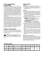
SPECIFICATIONS
Model
Capacity
Jack Size (L x W x H)
Min.
Height
Max.
Height
Saddle
Dia.
Volume of
Hyd. Oil
21025
2 1/2 Ton
25 3/8" x 13 1/8" x 6 1/2"
5"
19 1/2"
5"
150 ml
21030
3 Ton
27 1/2" x 13 3/8" x 6 3/8"
5 1/4"
19"
PREPARATION
Assembly
1. Assemble the 2-piece handle with provided bolt.
2. Insert handle into the handle sleeve. Tighten the bolt
on handle sleeve to prevent accidental removal of
handle while in use.
Before Use
1. Verify that the product and application are compatible,
if in doubt call Omega Tech Service (888) 332-6419.
2. Before using this product, read the operator's manual
completely and familiarize yourself thoroughly with
the product, its components and recognize the
hazards associated with its use.
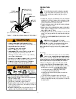
3. To familiarize yourself with basic operation, locate
and turn the release valve (handle):
a. Clockwise until firm resistance is felt to further
turning. This is the ‘
CLOSED
’ release valve
position used to
raise
the saddle.
b. Counter-clockwise, but no more than 1/2 turn
from the closed position. This is the ‘
OPEN
’
release valve position used to
lower
the saddle.
4. With saddle fully lowered, remove the oil filler plug.
Pump 6 to 8 full strokes. This will help release any
pressurized air which may be trapped within the
reservoir. Check oil level. Proper oil level will vary
from just covering the ram cylinder to 3/16” above it
as seen from the oil filler hole. Reinstall the oil filler
plug.
5. Ensure that jack rolls freely. Raise and lower the
unloaded saddle throughout the lifting range before
putting into service to ensure the pump operates
smoothly. Replace worn or damaged parts and
assemblies with Omega authorized replacement
parts only.
Bleeding / Venting Trapped Air
With the release valve in the OPEN position (3b.) and
with saddle fully lowered, locate and remove the oil filler
plug. Pump 6 to 8 full strokes. This will help release
any pressurized air which may be trapped within the
reservoir. Reinstall the oil filler plug.
SAFETY and GENERAL
INFORMATION
Save these instructions.
For your safety, read,
understand, and follow the information provided with
and on this jack before using. The owner and operator
of this equipment shall have an understanding of this
jack and safe operating procedures before attempting
to use. The owner and operator shall be aware that use
and repair of this product may require special skills and
knowledge. Instructions and safety information shall be
conveyed in the operator's native language before use
of this jack is authorized. If any doubt exists as to the
safe and proper use of this jack, remove from service
immediately.
Inspect before each use.
Do not use if broken, bent,
cracked or damaged parts are noted. Any jack that
appears damaged in any way, or operates abnormally
shall be removed from service immediately. If the jack
has been or suspected to have been subjected to a
shock load (a load dropped suddenly, unexpectedly
upon it), immediately discontinue use until jack has been
checked by a factory authorized service center (contact
distributor or manufacturer for list of authorized service
centers). It is recommended that an annual inspection
be done by qualified personnel. Labels and Operator's
Manuals are available from manufacturer.
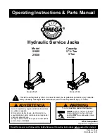
PRODUCT DESCRIPTION
Hydraulic Service Jack is designed to lift, but not
support, one end of a vehicle. Immediately after lifting,
loads must be supported by a pair of appropriately
rated jack stands.
NEVER
use hydraulic jack as stand-alone
device. After lifting,
immediately
support the
lifted vehicle with a pair of appropriately rated jack
stands.
!