

4
MAINTENANCE
Important: Use only good grade hydraulic jack oil. Avoid
mixing different types of fluid and NEVER use brake
fluid, turbine oil, transmission fluid, motor oil or glycerin.
Improper fluid can cause premature failure of the jack
and the potential for sudden and immediate loss of load.
We recommend Mobil DTE 13M or equivalent.
Adding oil
1. With saddle fully lowered set jack in its upright, level
position. Remove oil filler plug.
2. Fill with oil until ~3/16" above the inner cylinder as
seen from the oil filler hole. Reinstall the oil filler
plug.
Changing oil
For best performance and longest life, replace the
complete fluid supply at least once per year.
1. With saddle fully lowered, remove the oil filler plug.
2. Lay the jack on its side and drain the fluid into a
suitable container.
Note.
Dispose of hydraulic fluid in accordance with
local regulations.
3. Fill with oil until ~3/16" above the inner cylinder as
seen from the oil filler hole. Reinstall oil filler plug.
Lubrication
A periodic coating of light lubricating oil to pivot points,
axles and hinges will help to prevent rust and assure that
wheels, casters and pump assemblies move freely.
Cleaning
Periodically check the pump piston and ram for signs
of rust or corrosion. Clean as needed and wipe with
an oily cloth.
Note:
Never use sandpaper or abrasive material on
these surfaces!
Storage
When not in use, store the jack with saddle fully
lowered.
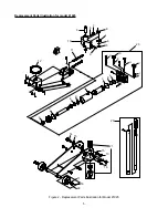
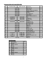
REPLACEMENT PARTS
(refer to page 5 thru 7)
Not all components of the jack are replacement items,
but are illustrated as a convenient reference of location
and position in the assembly sequence. When ordering
parts, please give the Model number, part number and
parts description. Call or write for current pricing:
SFA Companies 10939 N. Pomona Ave. Kansas City,
MO 64153, U.S.A. E-Mail: [email protected]
Tel: (888) 332-6419 Fax: (816) 891-6599
Website: http://www.omegalift.com
TROUBLESHOOTING
Symptom
Possible Causes
Corrective Action
Jack will not lift load
• Release valve not tightly closed
• Load is too heavy
• Ensure release valve tightly closed
• Consider higher capacity jack
Jack will lift, but not maintain
pressure
•
Release valve not tightly closed
• Hydraulic unit malfunction
•
Ensure release valve tightly closed
• Discontinue use, contact Omega
technical service
Jack will not lower after unloading • Reservoir overfilled
• Linkages binding
• Fluid level low
• Drain fluid to proper level
• Clean and lubricate moving parts
• Ensure proper fluid level
Poor lift performance
• Fluid level low
•
Air trapped in system
• Ensure proper fluid level
•
With ram fully retracted, remove oil
filler plug/screw to let pressurized
air escape. Reinstall oil filler plug
Will not lift to full extension
• Fluid level low
• Ensure proper fluid level


