9
Installation
The place where the machine will be kept and / or used must be in accordance with applicable laws and
ensure adequate protection from accidental damage, deterioration and weathering agents. The access ways
should provide enough clearance for handling the mixer without risk to the safety of people and the machine
itself. Flooring, walls and structures must comply with the applicable regulations and standards, and be suitable
for bearing the reference load plus an adequate safety factors; They must be easy to clean and disinfect. The
floor must be flat, not sloping, compact, and without holes and bumps. The in-house electrical and grounding
systems must comply with the applicable laws and regulations, and should be designed, manufactured,
maintained, and controlled by a licensed, qualified firm, if so required by law, with powers of testing and
releasing a statement of conformity. The in-house upstream switchboard should be fitted with efficient safeties
against any current overloads, short circuits, phase-to-phase, phase-neutral (if applicable), and phase-ground
faults.
TRANSPORTATION, HANDLING AND PLACEMENT
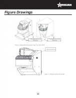
Depending on the final mixer application and contract agreements, mixers are packed (Figure 6 / A) on the
pallet and secured with straps. Alternatively (Figure 6 / B) they can be packed in a cardboard box, put on a
pallet and secured with straps (usually for EU countries) or even in a cage or wooden crate (countries outside
the European Community). Pallets and/or cages and/or boxes are loaded on the transport vehicle and secured
with crossbars and/or wooden blocks appropriately positioned/fastened to a load bearing part of the vehicle
in order to prevent misplacements during travel. To hoist and handle a pallet, cage or crate, use a lifting fork
of suitable capacity. Weight data are also stated on the mixer identification plate; Slip the lifting fork into the
special grooves at the base of the pallet/crate/cage until they protrude by at least 200 mm on the opposite side.
PLEASE NOTE:
Do not use handling systems, tools and equipment other than those that are described herein. When handling
and / or transporting the mixer or parts thereof take all the necessary precautions to avoid, or minimize,
the occurrence of risks to people, animals, and other assets. Remove the machine from its packaging,
separating the materials by type (plastic, wood, etc.) and deliver them to dedicated collection areas, assigned
to authorized persons for disposal in accordance with current environmental laws and regulations. Check
the machine and make sure there are no missing parts; if in doubt, consult the manufacturer. To remove an
unpacked mixer from the pallet, crate, or cage, lift it up using a strap of adequate capacity (the weight of the
machine is indicated on the plate as well as in this manual) slipped underneath the mixer head at the outlet
(see Figure 7) and hooked up to a lifting device of adequate capacity (jib cranes, bridge cranes, etc.). The
strap should be compliant to the relevant legal requirements and must have a maximum width of 40 mm and
a length so that each connecting length from below the head of the base to the hook of the lifting device is at
least equal to 1200 mm; so that the band remains flat and as close as possible to the column of the base: It is
forbidden to hang up the strap to the tips of a lifting fork as it might slip off and break away with consequent fall
of the mixer and risk of injuries to the bystanders; Also avoid swinging of the suspended mixer that may cause
instability of the forklift.
Lift the machine gently, avoiding jolts and vibrations; once raised it could tip slightly; this is absolutely normal.
Simply be careful to handle it with very gentle movements until it stands firmly on all wheels. Place the machine
in a safe and secure place, away from any risk of impacts and damages. The mixer standing on the floor with
its wheels can be moved around by simply pushing it; the two front wheels are pivoting, whilst the two rear
wheels are fixed. The working area around the machine must be kept as clear as possible from surrounding
Summary of Contents for MX-IT-0080-M
Page 20: ...20 Figure Drawings ...
Page 21: ...21 Figure Drawings ...
Page 22: ...22 Figure Drawings ...
Page 23: ...23 Figure Drawings ...
Page 24: ...24 Figure Drawings ...
Page 25: ...25 Figure Drawings ...
Page 26: ...26 Figure Drawings ...
Page 27: ...27 Figure Drawings ...
Page 28: ...28 Figure Drawings ...
Page 29: ...29 Figure Drawings ...
Page 30: ...30 Figure Drawings ...
Page 31: ...31 Figure Drawings ...
Page 32: ...32 Parts Breakdown Model MX IT 0080 M 49122 ...
Page 34: ...34 Electrical Schematics Model MX IT 0080 M 49122 ...
Page 35: ...35 Electrical Schematics Model MX IT 0080 M 49122 ...
Page 36: ...36 Electrical Schematics Model MX IT 0080 M 49122 ...


